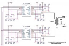
I just realized that Nelson published his Zen I/V converter and here is a slight modification to replace the two 10uf caps with a transformer.

LTspice file
Jfet Models
dave
LTspice file
Jfet Models
dave
Last edited:
completely logical ;
it's easier for you to make xformers than to make resistors

in any case - to keep things clean and safe - it's wise to decrease PS to +/-12V or - even better - to increase it slightly , and cascode Jfets
it's easier for you to make xformers than to make resistors
in any case - to keep things clean and safe - it's wise to decrease PS to +/-12V or - even better - to increase it slightly , and cascode Jfets
Since I make resistors all the time, don't you mean it is easier for me to make transformers than 10uf capacitors 🙂
In any event the low voltage drop of the transformer primary allows 15V supplies to be used which I guess could be spun as a green solution nearly halving the energy consumtion of the circuit.
I do want to say that outside of spice, this hasn't been tested yet so I'm just throwing it out there for discussion.
dave
Nice. Ideas/suggestions for the x-former? - Pat
A line-level transformer intended for push-pull dive and sufficiently gapped to handle the JFET bias currents. Perhaps, one of the amorphous core Lundahls would serve quite nicely, if not inexpensively, I should think.
sorry - I just didn't saw these 1K resistors still in drains (I'm sorta in hurry - some 8 hours from your time  )
)
😉
what about not having drain resistors at all ?
even if Jfet paralleling is necessary to keep L and Rdc of primary as low as possible .....
)😉
what about not having drain resistors at all ?
even if Jfet paralleling is necessary to keep L and Rdc of primary as low as possible .....
Drain resistors good.
You have to have the drain resistors so that you are not trying to drive the transformer only from the JFET drains, Their impedance is way too high and would cause both distortion and low-frequency roll-off with the transformer. Those resistors essentially present a 1k ohm source impedance for each primary winding.
Another huge advantage of transformer coupling this circuit is the dramatically increased PSRR. The cap coupled version has essentially a PSRR of zero, with respect to imbalanced power supply noise. This is due to the current-source like JFET drain nodes working against us. The transformer coupled version should have excellent PSRR due, again, to the current-source like drain nodes, but this time working in our favor.
sorry - I just didn't saw these 1K resistors still in drains (I'm sorta in hurry - some 8 hours from your time
😉
what about not having drain resistors at all ?
even if Jfet paralleling is necessary to keep L and Rdc of primary as low as possible .....
You have to have the drain resistors so that you are not trying to drive the transformer only from the JFET drains, Their impedance is way too high and would cause both distortion and low-frequency roll-off with the transformer. Those resistors essentially present a 1k ohm source impedance for each primary winding.
Another huge advantage of transformer coupling this circuit is the dramatically increased PSRR. The cap coupled version has essentially a PSRR of zero, with respect to imbalanced power supply noise. This is due to the current-source like JFET drain nodes working against us. The transformer coupled version should have excellent PSRR due, again, to the current-source like drain nodes, but this time working in our favor.
You have to have the drain resistors so that you are not trying to drive the transformer only from the JFET drains,.......
agree with everything ( even if I didn't quote entire post) - but I meant on custom made xformer ,optimized for that .
anyway - just a thought .......
agree with everything ( even if I didn't quote entire post) - but I meant on custom made xformer ,optimized for that .
anyway - just a thought .......
Yes, I see what you would hope to do. The problem would be that I don't believe any custom audio transformer could be made with a high enough primary inductance. Such a configuration as you're thinking is possible with tubes because they have an internal plate resistance appearing in parallel with their transconductance element.
A grounded source FET has no such internally parallel drain resistance and so act only like transconductance elements (high impedance current-source like nodes) as seen from their drains. BTW, this is also true of bipolar transistors and tube pentodes.
My bad
Dave, I just realized who you are. Whoops, sorry about the Lundahl suggestion.😱
It sounds as if you may be thinking of creating a transformer specifically for the Zen I/V circuit.
Since I make resistors all the time, don't you mean it is easier for me to make transformers than 10uf capacitors 🙂
dave
Dave, I just realized who you are. Whoops, sorry about the Lundahl suggestion.😱
It sounds as if you may be thinking of creating a transformer specifically for the Zen I/V circuit.
Hey Ken.
thanks for putting the operation of the circuit in better terms than I could ever do.
dave
thanks for putting the operation of the circuit in better terms than I could ever do.
dave
If you are prepared to use transformer, you might as well use a passive IV (10R resistor) and then a gain stage of 100 (any low noise phono gain circuit, or the "Susan Parker" pre).
No 2SJ74 required. Big advantage.
Patrick
No 2SJ74 required. Big advantage.
Patrick
Attachments
Last edited:
If you are prepared to use transformer, you might as well use a passive IV (10R resistor) and then a gain stage of 100 (any low noise phono gain circuit, or the "Susan Parker" pre).
No 2SJ74 required. Big advantage.
Patrick
I should think that most 40dB open loop voltage gain stages will have greater distortion than does Nelson's circuit in DAC IV service. Particularly so if they are solid state and anywhere near as simple. But, I could be wrong.
I don' know that 2SJ74s are any more difficult to obtain than many NOS tubes in popular use for diy. 2SJ109s are also an option. Also, I'm not understanding point as to what using a transformer has to do with the choice of also using a passive IV followed by a high voltage amplification stage.
If you are prepared to use transformer, you might as well use a passive IV (10R resistor) and then a gain stage of 100 (any low noise phono gain circuit, or the "Susan Parker" pre).
No 2SJ74 required. Big advantage.
Patrick
How do you couple to the grid and from the plate in your proposed scenario?
dave
The active part of the circuit I posted (wasn't my design in any case) has no gain.
It is a choke loaded JFET source follower. Hence also no plate and grid.
All the gain comes from the transformer.
And the DAC sees a linear passive device rather than the non-linear effective resistance of the sources in parallel of the complementary JFETs.
I presume that transformer properly done would have next to no distortion, especially when it is not current loaded by the gate of the JFETs.
If I did my sums right, then a pair of matched BF862s with a Tx 1:240 and 2x10 ohm at the DAC output will get me 4Vrms, balanced, with a pair of PCM1704 (+/- 1.2mA) and a bandwidth of about 100kHz. Output impedance is about 30 ohm per side. And quite reasonable PSRR. On top of that, you automatically get balanced output, and near constant current draw on a single supply rail.
You won't get that with the Zen IV. And the circuit is not more complicated.
The transformer will cost you a few bucks, but so would 2x 10uF MKP decoupling caps plus a fancy low noise dual rail power supply.
Only a suggestion for Tx lovers, nothing more.
And the 2SJ74 issue has nothing to do with availability, but capacitance (and hence bandwidth).
Patrick
Last edited:
Your proposed solution appears problematic for several reasons.
1. Transformers are not distortion free, just read their datasheets. Not only do they generate distortion, that distortion tends to be predominantly 3rd harmonic. While you don't explicitly say so, I assume that your suggested topology uses the BF862 as an output buffer because you mention it having a low 30 ohm output impedance. Voltage followers are not distortion free either, and whether the net distortion would be lower than that of the Pass/Slagle configuration is not so clear-cut. Grounded-gate is a relatively linear open loop gain mode.
2. I'm not aware of any 1:240 turn-ratio quality audio transformers. The highest turns ratio which comes readily to mind is about 1:37 from transformers intended for MC phono or ribbon microphone step-up applications.
3. If there were a 1:240 transformer, it's output impedance in the application you describe would be 2 x 10 x 240 x240 = 1,152,000 ohms. Even using BF862 JFETs with their low 10pF input capacitance in a source-follower configuration, that high of an transformer output impedance would result in a frequency response that was -6dB at only 13.8kHz.
Lastly, since Nelson's circuit drives the JFETs in grounded-gate mode, what is your specific concern about the 2SJ74's capacitance related bandwidth?
Yes, I see what you would hope to do. The problem would be that I don't believe any custom audio transformer could be made with a high enough primary inductance. Such a configuration as you're thinking is possible with tubes because they have an internal plate resistance appearing in parallel with their transconductance element.
A grounded source FET has no such internally parallel drain resistance and so act only like transconductance elements (high impedance current-source like nodes) as seen from their drains. BTW, this is also true of bipolar transistors and tube pentodes.
You can drive a transformer with a current-source if you put an appropriate load on the secondary. I've done it before. The reflected secondary loads the amplifying device. You can get flat output across the audio band as long as the secondary load is pure resistance.
I already does the same in more than few DACs ;
to my ears - loading DAC I output with reflected load is best - that way you're achieving linear transfer of entire combo .....
but wasn't in the mood for splitting the hair here .....
to my ears - loading DAC I output with reflected load is best - that way you're achieving linear transfer of entire combo .....
but wasn't in the mood for splitting the hair here .....
K&K use a Lundahl LL1674 transformer on their PCM1794 based RAKK DAC. An active or passive output is available. I still own the original version of the DAC with the passive output. Output impedance (off the top of my head) is 3k.
http://www.kandkaudio.com/digitalaudio.html
It's was the best digital I've ever heard, but I'm really not into CDs these days. Nothing wrong with transformers provided they are of high enough quality.
http://www.kandkaudio.com/digitalaudio.html
It's was the best digital I've ever heard, but I'm really not into CDs these days. Nothing wrong with transformers provided they are of high enough quality.
- Status
- Not open for further replies.
- Home
- Amplifiers
- Pass Labs
- Transformer output for zen I/V