Hello
I was thinking of building an audio amplifier. I have not decided on the details, eg what supply, what wattage, except I am not too keen on huge voltages across the rails.
I was thinking of a single sided design but that requires a trick at the end, some means of isolating the emitter of the output transistors from the speakers so we do not send DC down the speaker.
For that two options have been suggested to me: a capacitor or a transformer.
Assuming the transformer route, would you be able to advise me if it is possible and what type it would need to be and what calculations go behind it?
Many thanks
akis
you ve been told
something wrong ......single power sup means capacitor in the output .....
end of story nothing else except you are talking tubes
something wrong ......single power sup means capacitor in the output .....
end of story nothing else except you are talking tubes
Re: you ve been told
It's possible to build a solid state amp using traditional transformer coupling (like tubes) at low voltage and high current. Either single ended or push pull. No capacitor at the output.
For anything over a few watts, getting the transformers is probably going to be a pain in the ****, but not impossible. Before you go asking why anyone would want to do this, the obvious answer is for the fun of it.
sakis said:end of story nothing else except you are talking tubes
It's possible to build a solid state amp using traditional transformer coupling (like tubes) at low voltage and high current. Either single ended or push pull. No capacitor at the output.
For anything over a few watts, getting the transformers is probably going to be a pain in the ****, but not impossible. Before you go asking why anyone would want to do this, the obvious answer is for the fun of it.
akis said:For that two options have been suggested to me: a capacitor or a transformer.
What about a bridge?
Re: Re: Transformer in the output
Twice as many transistors. But you do get to use up a bunch of low voltage stuff (like 2N3055s) without the expense or aggravation of an OPT.
analog_sa said:
What about a bridge?
Twice as many transistors. But you do get to use up a bunch of low voltage stuff (like 2N3055s) without the expense or aggravation of an OPT.
solid state RF amps use transformer output coupling all the time (for impedance matching) with both single ended and bipolar supplies. to do this with high power audio frequency would require a very large transformer.
Hi akis
Sowters will generally wind transformers to specification, but they are expensive.
A 50-watt output is going to need about 1.5 inch core (USA EI150, imperial pattern #120), and you'll have to drive it from push-pull, not a SE amp. (unless you use a capacitor first) But you get to specify the operating voltage!
Here's how I calculate it:
define a characteristic dimension a as the outer limb width of the core (for a waste free EI core, and which also equals the width of the "I" plates and bobbin window; the central core is then 2a)
a=[power/(4.44x12xFBSUJ)]^0.25
where B=max flux (tesla)
f=lowest frequency (Hz)
S=stack height to width ratio (normally 1)
U= utilisation factor of copper to window space (a number<1)
J=max current density in wire (A/sq m)
Bet you want to know what these should be?
The main problem I suspect will be obtaining the cores, bobbin and mounting hardware. Copper is probably twice the price since I last bought any, and for a largish transformer you'll need around 1 kg of wire or thereabouts.
And driving such a beast will not be easy. It used to be done in the 1950's with another transformer, but it is possible to arrange capacitor-driven phase splitters with some difficulties.
I happen to think that capacitor coupled amps should be OK these days with modern low inductance, low impedance power supply types, but many will say don't. I have not checked the distortion arising in such caps, but they ought to be better than the older designs.
For a first amp I would strongly recommend a cap output. If you short something, there is a better chance that not everything will be destroyed. direct coupled amps which are not debugged can wreck everything easily!
cheers
John
Hi
I built a small (couple watts) amp once using a transformer output. The output transfo secondary Z was 8 Ohms. There was only 2 PNP transistors in the circuit. I used an input transformer to split the phase, amplified to the centertapped primary output transformer to match Z to the speaker. Super simple, but not exactly "high end".
I built a small (couple watts) amp once using a transformer output. The output transfo secondary Z was 8 Ohms. There was only 2 PNP transistors in the circuit. I used an input transformer to split the phase, amplified to the centertapped primary output transformer to match Z to the speaker. Super simple, but not exactly "high end".
Hello
I was sure I replied but cannot see my reply anywhere.
To elaborate, I have not decided on power yet, but I presume a single supply rail of 60 Volts sounds safe enough if you touch it.
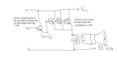
I was planning to have a bunch of transistors in common collector configuration at the output, supposing we have the emiiter at, say, 30 Volts and supposing that we do not care about swinging end to end, say we only care to swing +/-20 volts from there, so we leave 10 volts on either side.
That would give us an output voltage of 14 Volt RMS, ie a theoretical power of 25 Watt RMS into 8 Ohm or 50 Watts into 4 Ohms, assuming we could somehow transfer that power.
So now we have a transistors emitter idling at 30 Volts and wanting to swing from 10 to 50 Volts and somehow we need to somehow connect that to the speaker.
This is where I need some ideas/help 🙂
Employing solutions involving large number of transistors or other complicated schemes defeats my purpose.
Of course I am quite ready to accept that what I ask is either impossible or completely impractical (eg requires more transistors than a push-pull design).
I was sure I replied but cannot see my reply anywhere.
To elaborate, I have not decided on power yet, but I presume a single supply rail of 60 Volts sounds safe enough if you touch it.
I was planning to have a bunch of transistors in common collector configuration at the output, supposing we have the emiiter at, say, 30 Volts and supposing that we do not care about swinging end to end, say we only care to swing +/-20 volts from there, so we leave 10 volts on either side.
That would give us an output voltage of 14 Volt RMS, ie a theoretical power of 25 Watt RMS into 8 Ohm or 50 Watts into 4 Ohms, assuming we could somehow transfer that power.
So now we have a transistors emitter idling at 30 Volts and wanting to swing from 10 to 50 Volts and somehow we need to somehow connect that to the speaker.
This is where I need some ideas/help 🙂
Employing solutions involving large number of transistors or other complicated schemes defeats my purpose.
Of course I am quite ready to accept that what I ask is either impossible or completely impractical (eg requires more transistors than a push-pull design).
akis said:Hello
I was sure I replied but cannot see my reply anywhere.
To elaborate, I have not decided on power yet, but I presume a single supply rail of 60 Volts sounds safe enough if you touch it.
I was planning to have a bunch of transistors in common collector configuration at the output, supposing we have the emiiter at, say, 30 Volts and supposing that we do not care about swinging end to end, say we only care to swing +/-20 volts from there, so we leave 10 volts on either side.
That would give us an output voltage of 14 Volt RMS, ie a theoretical power of 25 Watt RMS into 8 Ohm or 50 Watts into 4 Ohms, assuming we could somehow transfer that power.
So now we have a transistors emitter idling at 30 Volts and wanting to swing from 10 to 50 Volts and somehow we need to somehow connect that to the speaker.
This is where I need some ideas/help 🙂
Employing solutions involving large number of transistors or other complicated schemes defeats my purpose.
Of course I am quite ready to accept that what I ask is either impossible or completely impractical (eg requires more transistors than a push-pull design).
I would tend to go for a more traditional design with split power supplies. No need for caps, transformers or lots of extra transistors on the output then.
Some of my earlier amp designs used +/-40 volts but they lacked the dynamic range required by CD's.
Transients were clipped with not a lot of volume. I now go for at least +/- 60 volts to get a good range.
Thanks, i found this as the most useful:
http://sound.westhost.com/jll_hood.htm
However I do not understand why go to lengths to avoid the output transformer.
My idea is like this (please excuse the poor quality of the sketch):
http://sound.westhost.com/jll_hood.htm
However I do not understand why go to lengths to avoid the output transformer.
My idea is like this (please excuse the poor quality of the sketch):
Attachments

I have assembled, down the eigthies, a circuit alike this one
And sounded good.... i had some problems into very deep bass and very high trebles.... i think my transformer was not very good those days...was made by myself following the techniques, the uses from those early days.
Transformers to audio are completelly different, into their construction , compared to transformers to AC mains... both are for AC, but the second one will not operate into 60 hertz only.
They are the "quality limiting factor"..... reason why i have appreciation on tubes, but with some "reserve", because they use transformers too.
regards,
Carlos
akis said:However I do not understand why go to lengths to avoid the output transformer.
Seeing you've chosen the most difficult type of output transformer (unbal dc) you'll know when you finish the first seventeen prototypes 🙂
akis said:.... some means of isolating the emitter of the output transistors from the speakers
so we do not send DC down the speaker.
For that two options have been suggested to me:
a capacitor or a transformer.
I will not go into details to try to figure out what is best, capacitor / transformer.
I only have done this observation about transistor amplifiers
which use single voltage supply:
99 out of 100 amplifiers use Output Capacitor
... if transformer output was better or even close to equally good,
we would expect to see a few more using this solution,
wouldn't we?
Because those building amplifiers are often quite clever.
Lineup
Supposing I take an *old* speaker or the appropriate wattage and connect it straight. The cone of the speaker will move to one direction and stay there for sure, but nevertheless it will be presenting an impedance of 8 Ohm to my emitter even down to DC! Am I right ?
That is the kind of transformer I am looking for.
That is the kind of transformer I am looking for.
akis said:Supposing I take an *old* speaker or the appropriate wattage and connect it straight. The cone of the speaker will move to one direction and stay there for sure, but nevertheless it will be presenting an impedance of 8 Ohm to my emitter even down to DC! Am I right ?
That is the kind of transformer I am looking for.
DC into a speaker is not recommended.
There is little impedance to resist the flow of current and it will fry your voice coil.
akis said:
That is the kind of transformer I am looking for.
I do not understand why ????
you want to use some hard to find, expensive output trafo.
Because, I am pretty sure, you will not get any better sound quality,
than if using The Simple, Lower Cost, easy to find Capacitor solution.
This solution which 99 out of 100 would go for.
Because they are clever 😉 And not the opposite
I mean, Why give yourself more trouble and headache. Than is necessary.
Be smart!
Lineup
I hope you have visited, as recommended by a previous poster,
Susan Parker website: http://www.audiophonics.com/
She has built a high qualilty MOSFET amp with Output Transformer.
Here is information of such an output trafo:
http://www.audiophonics.com/audiophonics-zeus-out-tx-75w.html
Weight = 4.7 kg
Price = ???

Susan Parker website: http://www.audiophonics.com/
She has built a high qualilty MOSFET amp with Output Transformer.
Here is information of such an output trafo:
http://www.audiophonics.com/audiophonics-zeus-out-tx-75w.html
Weight = 4.7 kg
Price = ???
- Status
- Not open for further replies.
- Home
- Amplifiers
- Solid State
- Transformer in the output