1. Post # 18 has a Triode Wired 807 in parallel with a Beam Tetrode wired 807 for the "Push" output; and likewise, a Triode Wired 807 and Beam Tetrode Wired 807 for the "Pull" output.
You get 2 unequal sets of curves for "Push" and 2 unequal sets of curves for "Pull". Hmmm.
2. Having a 100 Ohm cathode "Balance" resistor without sense resistors makes it hard to know when it is set for 2 equal currents, and for sure you can not know if it is 4 equal currents.
Like Lingwendil, I think 4 individual sense/balance resistors are in order.
Perhaps 4 each 50 Ohm sense resistors will at least allow easy measurements to check how well-matched or badly-matched the 4 currents are at the quiescent operating state.
Just remember, the 4 curves will not match.
3. An 807 plate resistor with a wire wound over it (RF anti parasitic choke), can easily be covered with a large diameter Heat Shrink Tube.
Anyway, children's fingers should not even be allowed to come close to any hot tube, let alone an uncovered HV connection.
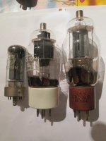
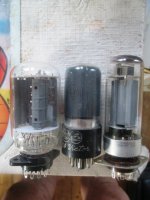
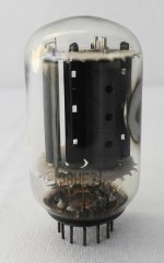
4. I have a number of 807 tubes, and they may, or may not be matched. But since I am using them in Single Ended, that does not much matter.
There are still 807 NOS tubes available.
Oh, . . . 807 tubes are not pentodes.
You get 2 unequal sets of curves for "Push" and 2 unequal sets of curves for "Pull". Hmmm.
2. Having a 100 Ohm cathode "Balance" resistor without sense resistors makes it hard to know when it is set for 2 equal currents, and for sure you can not know if it is 4 equal currents.
Like Lingwendil, I think 4 individual sense/balance resistors are in order.
Perhaps 4 each 50 Ohm sense resistors will at least allow easy measurements to check how well-matched or badly-matched the 4 currents are at the quiescent operating state.
Just remember, the 4 curves will not match.
3. An 807 plate resistor with a wire wound over it (RF anti parasitic choke), can easily be covered with a large diameter Heat Shrink Tube.
Anyway, children's fingers should not even be allowed to come close to any hot tube, let alone an uncovered HV connection.
4. I have a number of 807 tubes, and they may, or may not be matched. But since I am using them in Single Ended, that does not much matter.
There are still 807 NOS tubes available.
Oh, . . . 807 tubes are not pentodes.
Last edited:
1. Post # 18 has a Triode Wired 807 in parallel with a Beam Tetrode wired 807
There are still 807 NOS tubes available.
Oh, . . . 807 tubes are not pentodes.
1/ too true, forgot to look at that weirdo.
Also the HT is waaaay over 400V & even the tetrode thingy is even over 400V.
The power supply is choke input filter, but they derive a screen supply from it via a voltage divider resistor chain.
Not sensible, the regulation would be awful, and a sagging power supply would be reflected right the way up into the audio section.
(on my amps they stick the anode through a seperate rectifier with choke input filter, and the screens on a seperate winding with a capacitor input filter & choke. I changed it to Si rectifiers, then put 2 gas regulators into the screen supply in series to give exactly 300V all the time, as well as feeding the driver stages with a HT with almost non existent sag and ripple. The screen supply is the only one to have a [enlarged] valve rectifier because it brings the output valves slowly online. )
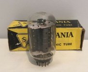
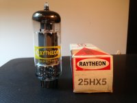
NOS 807s there are 1000s of the things inc all the Russian ones both UX5 (Г-807) and Octal versions (6П7С), two a penny.
Some nice red base Ulyanovsk 807 out there for ~$6USD/pc for those inclined. 300 volts (regulated via 0D3 x2) screen, 450-550 volts plate is a good way to run them in the gear I've worked them into. I don't personally run plate cap tubes at home (a three year old and a cat are too curious to leave such things be) but wouldn't hesitate to run them in variant of the 6L6GC AB2 amp from the now legendary thread a while back.
A zener stack feeding a source follower with a long RC time constant to feed the gate is a good simple soft start screen supply for those inclined 🙂
A zener stack feeding a source follower with a long RC time constant to feed the gate is a good simple soft start screen supply for those inclined 🙂
No need to use a TOP CAP version, dunno where you get your Russian prices.
The Г-807 I can get them in Russia from anything from 1.5USD to 10.
100 rouble or so about 1.50USD for 6П7С.
British 255m** without top cap max about 10 quid NOS.
Best deal/quality out there.
The Russians make a tiny little 150V gas regulator сг5б which has no equivalent in the west,- brilliant and more reliable than a zener. 2 x 150=300. Cost about 1USD.
Dead easy to drop into a simple cathode follower as a minimal parts count high current regulator, works great.
Perfect screen regulation has always been the way to get low distortion and high output from those old Yankee coke bottles.
Note:-
On the "Loctal 807"**, heater is 1 & 8.
Anode is on 2.
screen g2 on 3
K/bp on 4 & 7
2 seperate pins for g1 - 5 & 6
They are all rated the same -Loctal sockets can take a lot more volts. (small pins).
The top cap version is different:-
2, 4 , 7 are K/bp
all the others the same g2 on 3
5, 6 - g1
Attachments
Last edited:
Completely pointless.
Much better to use TV scan stuff, better and cheaper.
The xxHE7 has twice the gain of the 807, is quoted at conducting 1/4 an amp, with peak capability not far short of 1A at 500V, and is the same size as a 6V6.
It's also still on the 1USD lists.
(A pair in parallel starts looking like mosfet style current capabilities! A peak current capability of 1.5A!)
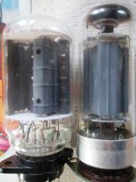
When you put them side by side the HE7 anode is actually LARGER than the last high quality 807s made,-
the STC version without top cap.
Officially if you don't use the internal damper diode (which can be quite useful) they can happily manage 17W without overheating, never mind red plate, (better than some of my old 807 samples).
It also has much more linear curves.
2 of them in parallel takes up less space than any 807, and gives a guaranteed 35W Anode valve
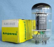
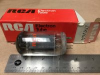
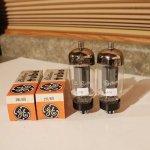
Here's the different NOS options with their brand new old stock bases.
Technology moved on a lot from 1935 to 1965-68, it's like comparing an old 78rpm mono shellac with a modern stereo 33rpm vinyl..
Much better to use TV scan stuff, better and cheaper.
The xxHE7 has twice the gain of the 807, is quoted at conducting 1/4 an amp, with peak capability not far short of 1A at 500V, and is the same size as a 6V6.
It's also still on the 1USD lists.
(A pair in parallel starts looking like mosfet style current capabilities! A peak current capability of 1.5A!)
When you put them side by side the HE7 anode is actually LARGER than the last high quality 807s made,-
the STC version without top cap.
Officially if you don't use the internal damper diode (which can be quite useful) they can happily manage 17W without overheating, never mind red plate, (better than some of my old 807 samples).
It also has much more linear curves.
2 of them in parallel takes up less space than any 807, and gives a guaranteed 35W Anode valve
Here's the different NOS options with their brand new old stock bases.
Technology moved on a lot from 1935 to 1965-68, it's like comparing an old 78rpm mono shellac with a modern stereo 33rpm vinyl..
Attachments
Last edited:
Gratifying to see someone else has noticed the xxHE7 tubes!
$1 tube.
The 38HE7 version has the pentode heater alone between pins 10 and 12 (for about 80% of the tubes I've seen), so 21V at 0.45 Amp heater then. These tubes use a lower grid 2 voltage than an 807, so not useable directly for UL designs.
I noticed one day that they were rated at close to half the old 42KN6 tube (old version with two parallel pentodes inside), so I paralleled up two of them and compared that with a vintage 42KN6 on the curve tracer. The same!
George (Tubelab) commented once that the older version of the 42KN6 sounded quite good for audio. So you can get a vintage 42KN6 equiv. for $2.
Without the damper diode operating in the bottle, I've heuristically rated the 38HE7 at 15 Watts for Horiz. deflection duty, for comparison with other TV tubes. (that's half of the 42KN6) Horizontal TV Sweep pentodes seem to be up-rate-able by around 30% for audio tube use. So 18 or 20 Watts Pdiss max. in that mode.
The xxHE7 tubes are very nearly the same as the full size 21HB5/A tube (18 Watts TV Sweep, the plate size on xxHB5 is similar to many 24 Watt Sweep tubes), except xxHE7 have a trimmed down plate to fit in the bottle with the damper diode (but same length plate as the xxHB5). 21HB5 is rated for 18 Watts TV Sweep duty.
The xxHE7 has a skosh better triode curves than the 21HB5 when traced in triode mode. (slightly less roll-over in the triode curves)
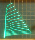
38HE7 triode mode curves below. I think these were 20 mA/div Vert., 25V/div Horiz. and around 7.5 V steps. (internal Mu 4.2)
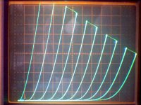
and 38HE7 pentode curves. 50V/div Horiz., 50 mA/div Vert., 1.5V steps, 117Vg2
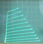
38HE7 works good in "Crazy drive" too, 50V/div Horiz., 50 mA/div Vert., 7V steps, last pic
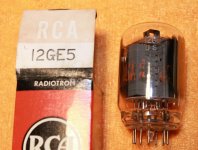
38HE7 AND 21HB5A tube pics
$1 tube.
The 38HE7 version has the pentode heater alone between pins 10 and 12 (for about 80% of the tubes I've seen), so 21V at 0.45 Amp heater then. These tubes use a lower grid 2 voltage than an 807, so not useable directly for UL designs.
I noticed one day that they were rated at close to half the old 42KN6 tube (old version with two parallel pentodes inside), so I paralleled up two of them and compared that with a vintage 42KN6 on the curve tracer. The same!
George (Tubelab) commented once that the older version of the 42KN6 sounded quite good for audio. So you can get a vintage 42KN6 equiv. for $2.
Without the damper diode operating in the bottle, I've heuristically rated the 38HE7 at 15 Watts for Horiz. deflection duty, for comparison with other TV tubes. (that's half of the 42KN6) Horizontal TV Sweep pentodes seem to be up-rate-able by around 30% for audio tube use. So 18 or 20 Watts Pdiss max. in that mode.
The xxHE7 tubes are very nearly the same as the full size 21HB5/A tube (18 Watts TV Sweep, the plate size on xxHB5 is similar to many 24 Watt Sweep tubes), except xxHE7 have a trimmed down plate to fit in the bottle with the damper diode (but same length plate as the xxHB5). 21HB5 is rated for 18 Watts TV Sweep duty.
The xxHE7 has a skosh better triode curves than the 21HB5 when traced in triode mode. (slightly less roll-over in the triode curves)
38HE7 triode mode curves below. I think these were 20 mA/div Vert., 25V/div Horiz. and around 7.5 V steps. (internal Mu 4.2)
and 38HE7 pentode curves. 50V/div Horiz., 50 mA/div Vert., 1.5V steps, 117Vg2
38HE7 works good in "Crazy drive" too, 50V/div Horiz., 50 mA/div Vert., 7V steps, last pic
38HE7 AND 21HB5A tube pics
Attachments
Last edited:
Yes I had already figured out the xxHE7 had a pile of good stuff lurking in there, but bear in mind we never had 12 pin valves ever in Europe, so it's taken me quite an effort to get them over inc NOS sockets to go with them...
I had also figured out if you buy the rarer 58v version you wire the 4 heaters in series across 230V, like in a TV, or 2 pairs in series direct across 115V.
What's not to like?
No need for a heater transformer, and if you use the 4 diodes you got yourself a high perveance full bridge rectifier to go with it with minimal voltage drop.
In fact I worked out the xxHE7 is the archetypal ideal series pass/regulator valve, probably even better maybe than the larger STC S11E12 I got lurking here, another very late high perveance beast from the 70s with abilities to conduct 400m/a at 800V.
Triode connected, works at same voltages as 807 but with no top cap, 4x the gain of the 807, and much smaller with octal base,conservative mil ratings:-
Pa <28W
costs peanuts cos nobody wants them.

Another great one is the xU10 which I bought loads of..
basically a very high quality well matched 7247 with an extra triode in there so it can make one preamp, and phase splitter in one glass.
You can wire the heaters for that off a lithium cell battery then and power it off a SMPS.
I found quite often the seperate sections were absolutely identical, and it's a heck of a lot cheaper than any NOS 12AX7 combo (12DW7) nowadays.
Loads of reasons to give up on 1935 valve designs, that's just 2 of them.
I gotta say I get really confused between smoking amps and tubelabs (George?).
You all seem to be in there to see when you can get stuff to melt and managed to blow up the Mosfets instead. 😀
I had also figured out if you buy the rarer 58v version you wire the 4 heaters in series across 230V, like in a TV, or 2 pairs in series direct across 115V.
What's not to like?
No need for a heater transformer, and if you use the 4 diodes you got yourself a high perveance full bridge rectifier to go with it with minimal voltage drop.
In fact I worked out the xxHE7 is the archetypal ideal series pass/regulator valve, probably even better maybe than the larger STC S11E12 I got lurking here, another very late high perveance beast from the 70s with abilities to conduct 400m/a at 800V.
Triode connected, works at same voltages as 807 but with no top cap, 4x the gain of the 807, and much smaller with octal base,conservative mil ratings:-
Pa <28W
costs peanuts cos nobody wants them.
Another great one is the xU10 which I bought loads of..
basically a very high quality well matched 7247 with an extra triode in there so it can make one preamp, and phase splitter in one glass.
You can wire the heaters for that off a lithium cell battery then and power it off a SMPS.
I found quite often the seperate sections were absolutely identical, and it's a heck of a lot cheaper than any NOS 12AX7 combo (12DW7) nowadays.
Loads of reasons to give up on 1935 valve designs, that's just 2 of them.
I gotta say I get really confused between smoking amps and tubelabs (George?).
You all seem to be in there to see when you can get stuff to melt and managed to blow up the Mosfets instead. 😀
Last edited:
I gotta say I get really confused between smoking amps and tubelabs (George?).
You all seem to be in there to see when you can get stuff to melt and managed to blow up the Mosfets instead.
I think George (Tubelab) still holds the record there: 😀
https://www.diyaudio.com/forums/tubes-valves/211254-magnificent-television-tubes-88.html#post5118740
The delivery guys here hold the real record (2nd pic)
Those STC S11E12 regulator tubes do look nice, but you must have bought all 300 of them already. Now $26 on Fleecebay.
Attachments

Last edited:
We don't need to buy on rip-off bay in England, there's at least 4 wholesalers for valves, and they are an easy crowd to get on with and do deals.
Some of them have been trading since when the things were still being made!
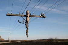
What on earth happened to that telegraph pole?
The ones stuck in bogland here and over the border are now routinely made of concrete.
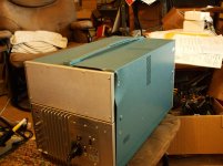
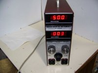
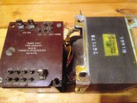
I decided to make my own regulated power supply at last now I got one of those nice Parmeko oil filled transformers and a scrap chassis.
It's so nice to be able to vary the bias, the anode & screen voltages all seperately and find the points of ideal quiescent current v OPT load.
Having said that, a 50W dummy load is starting to feel decidely lighweight.
I have to invest in some proper 200W resistor packs, because I came close to frying the 50W one last spring. (burnt my thumb badly on it!).
Some of them have been trading since when the things were still being made!
What on earth happened to that telegraph pole?
The ones stuck in bogland here and over the border are now routinely made of concrete.
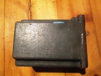
I decided to make my own regulated power supply at last now I got one of those nice Parmeko oil filled transformers and a scrap chassis.
It's so nice to be able to vary the bias, the anode & screen voltages all seperately and find the points of ideal quiescent current v OPT load.
Having said that, a 50W dummy load is starting to feel decidely lighweight.
I have to invest in some proper 200W resistor packs, because I came close to frying the 50W one last spring. (burnt my thumb badly on it!).
What on earth happened to that telegraph pole?
Was a picture from the Web, probably a brush fire or crop burn from a discarded cigarette. Was just perfect for the joke posting. Just needed a burnt out 6LW6 strapped to the pole.
I decided to make my own regulated power supply at last now I got one of those nice Parmeko oil filled transformers and a scrap chassis.
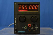
Those fancy Parmeko xfmrs are definitely expensive on Fleece bay. I did build a heavy Variac/Hammond xfmr variable B+ supply once. But have since found Hoefer PS500XT (later models, post 1994 with a fan in back) and Xantrex XT 250-0.25 (for grid 2 supply) to be suitable, light weight and inexpensive (at times, patience...). Regulated and current limited.
I have to invest in some proper 200W resistor packs, because I came close to frying the 50W one last spring. (burnt my thumb badly on it!).
I put some 50 Watt resistors (series/parallel) on a heatsink with a fan.
My next project is a crossover distortion analyzer for push-pull design. Gain versus input V as a graphic CRT display.
I guess we should return to the 807 topic.
Upgrade tubes: 😀
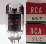
12GE5/12JN6, 38HE7, 12GT5, 22JR6, 22JG6, 6JC5, 21HB5/A, 21JV6, 6EX6, 6CB5A, 21LG6, 17/22KV6, 26DQ5, 6HJ5, 35LR6, 36MC6, 42KN6, 26LX6, 6KG6/EL509, 26/36LW6 ....
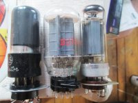
On a more constructive note, I would recommend tubes -without- top caps for home use:
12AV5, 6LU8, 25HX5, 6V6, 6L6GC..., 12GE5/12JN6, 38HE7, 12GT5, 22JR6, 22JG6, 6JC5, 21HB5/A, 21JV6, 17/22KV6, 6HJ5
Attachments
Last edited:
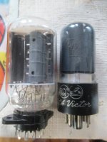
The 2nd one in is a 6V6 in drag. (6HE5).
Vertical deflect valve. (Ie. class A fixed freq amp as you rightly pointed out.), just a double sized cathode & therefore capable of being stung with 1/4 amp peak cathode currents & 2.5Kv nasties.
TBQH in parallel PP triode strapped, probably beats the pants off any 807.
I think we're exhausting the subject.
I try to avoid buying stuff off E-rip-off these days, because it's like flying with Lo-cost airlines, you usually find out getting stuff off a genuine airline usually ends up cheaper without all the hassles that come with it, and far more flexible.
Last top class Parmeko I got was brand new from a well known UK retailer, he just didn't have a schematic for it at all, so sold it to me for 60 quid.
After 30mins with a Variac all was sorted, and it's now sitting inside a 75w 807 powered US made GUITAR amp, which needed an urgent conversion to EU 230V.
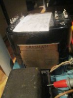
This last one I got was a Gresham which was to all intents and purposes identical but more powerful again, - all oil filled, so can be maxxed out constantly without smoking.
Basically if you do a constant search for stuff like Hiwatt (Partridge), Gardners, Parmeko leics (was started by Partridge), Gresham, Vortexion, and another of the greats of the past UK audio industry you inevitably end up hauling up bargains.
That way I pulled up this Parmeko heater transformer for dual 813s wound 10V CT, and with included 100V bias supply... I think it cost me 30 UKP only last november!
The DR200 transformer wasn't expensive...good for 800V. (about 60 quid!)
And of course this 500W 1000V beast I fished out of a scrap yard for a fiver some years ago.
In Europe of course, the best bargains are to be had by going to one of the 1/2 dozen Eastern Europe co.s like in Poland, or so I am told.
I'm a strong believer the secret to good amps is top quality transformers & chokes, but there's nothing new there.
...Bit like building any decent race engine, unless you start with a decent block, rods, and crank, you can FORGET IT!
Vertical deflect valve. (Ie. class A fixed freq amp as you rightly pointed out.), just a double sized cathode & therefore capable of being stung with 1/4 amp peak cathode currents & 2.5Kv nasties.
TBQH in parallel PP triode strapped, probably beats the pants off any 807.
I think we're exhausting the subject.
I try to avoid buying stuff off E-rip-off these days, because it's like flying with Lo-cost airlines, you usually find out getting stuff off a genuine airline usually ends up cheaper without all the hassles that come with it, and far more flexible.
Last top class Parmeko I got was brand new from a well known UK retailer, he just didn't have a schematic for it at all, so sold it to me for 60 quid.
After 30mins with a Variac all was sorted, and it's now sitting inside a 75w 807 powered US made GUITAR amp, which needed an urgent conversion to EU 230V.
This last one I got was a Gresham which was to all intents and purposes identical but more powerful again, - all oil filled, so can be maxxed out constantly without smoking.
Basically if you do a constant search for stuff like Hiwatt (Partridge), Gardners, Parmeko leics (was started by Partridge), Gresham, Vortexion, and another of the greats of the past UK audio industry you inevitably end up hauling up bargains.
That way I pulled up this Parmeko heater transformer for dual 813s wound 10V CT, and with included 100V bias supply... I think it cost me 30 UKP only last november!
The DR200 transformer wasn't expensive...good for 800V. (about 60 quid!)
And of course this 500W 1000V beast I fished out of a scrap yard for a fiver some years ago.
In Europe of course, the best bargains are to be had by going to one of the 1/2 dozen Eastern Europe co.s like in Poland, or so I am told.
I'm a strong believer the secret to good amps is top quality transformers & chokes, but there's nothing new there.
...Bit like building any decent race engine, unless you start with a decent block, rods, and crank, you can FORGET IT!
Attachments

Last edited:
Was a picture from the Web, probably a brush fire or crop burn from a discarded cigarette....
Looked rotten to me. Even termites. When the last strand of wood from ground to top blew-off, dinner was done, the top-stub could hang there forever. And a termite-nest might be one place and not under the next pole.
In Image Search it comes up "Not PhotoShop!" a lot. Never trust the internet.
"This Russian telephone pole seems like it has to be the result of Photoshop magic, but it’s totally real. Over the years, the wood slowly rotted away, leaving the top half of the pole to dangle precariously on the electrical wires."
Appear To Be Photoshopped But
Looking at that "Not Photo-shopped" site, they also have this bent tracks picture, which they say is from an earthquake. But I don't see any other disrupted ground around them. I think this was more likely a very hot day that made the tracks expand lengthwise and buckle up. (us in the know, of course, do see the symmetrical passage of a titanic EM wave from a 6LW6 putting out 600 Watts momentarily! 😎 )
On the hanging pole, not sure what goes on there. It does look kinda black in places and the field looks black, like it might have burned over. But then there is black rot too. Who knows?? And Creosote? We used to collect the glass insulators from discarded pole tops along the road, from maintenance I assume, while hiking in the Boy Scouts. Could be some contribution from firearm target practice too, but I don't see any shattered insulators. Must have made some interesting wire singing sounds in the wind, loved listening to that in the countryside with the old individual copper coated steel telephone wires.
On the hanging pole, not sure what goes on there. It does look kinda black in places and the field looks black, like it might have burned over. But then there is black rot too. Who knows?? And Creosote? We used to collect the glass insulators from discarded pole tops along the road, from maintenance I assume, while hiking in the Boy Scouts. Could be some contribution from firearm target practice too, but I don't see any shattered insulators. Must have made some interesting wire singing sounds in the wind, loved listening to that in the countryside with the old individual copper coated steel telephone wires.
Attachments

Last edited:
Hmmm, if the telephone wires were to go East-West, then the Earth's magnetic field would cross them at 90 deg. So one could maybe activate the singing wires by applying AC current thru them. Could arrange the wire tensions to give different tone ranges. Then program the currents to play tunes.
Just sayin', for those who have already built the ultimate tube amplifier. A natural singing guitar on a giant scale. Use enough wires, and you could use it as a mult-crossover speaker. Although the natural wining wind sound from old telephone wires was undoubtedly a high harmonic mechanical waveform on the wire. Some more design thought needed. Maybe just put alternating Neodymium magnets, spaced along the ground, to get the correct resonant wavelengths.
Ah-Ha! A brilliant deduction now.
The wires on the hanging pole were singing in the wind for many years (in the pre-hanging condition) and that fatigued the wood pole (acting like a sound board from wire tension changes), causing it to rattle apart over time, and disintegrate, leaving the hanging pole pictured. 😎
Maybe explaining why the poles had to be maintained all the time. And they thought it was woodpeckers all this time.
Last edited:
Hmmm, if the telephone wires were to go East-West, then the Earth's magnetic field would cross them at 90 deg. So one could maybe activate the singing wires by applying AC current thru them. Could arrange the wire tensions to give different tone ranges.
Talking about magnetic fields,-
Just listening to a mountain of bollox from the BBC about new "green energy transition" & the new "smart grids" run and designed by very stupid people,- built in single points of failure et al...forgetting we side stepped a "carrington event" only recently,-
while "the wrong kind of snow" stranded TGVs in the channel tunnel and last summer's UK grid failure stranding and leaving a large part of the UK's rail system with no power for hours.
On Friday 9th August the UK experienced major electrical power failures effecting transport and infrastructure across the country.
“A worst case outcome of any disturbance for an electricity system operator is that the whole system goes down. Recovery is then massively challenging, not just for users of electricity such as the railway companies but also the power system operators.
Both perfect examples of single points of failure, but then fobbed off and excused in the mass media as "rare events".

Such an event happening in 2020 would make the pole look like small potatoes, but it's not IF but WHEN.The solar storm of 2012 was an unusually large and strong coronal mass ejection (CME) event that occurred on July 23 that year. It missed the Earth with a margin of approximately nine days,
Compare it with the outage of a massive proportion of the developed world's infrastructure.
It would make the remoter places in Africa, northern Russsia and South America look quite advanced.
But hey we are down an amusing back lane from transformer impedance world, here we are discussing what it's like to burn them out and melt them... something any decent guitarist knows plenty about.
These were opposite sides of the earth on different dates and not photoshopped.
Attachments


Last edited:
Ah-Ha! A brilliant deduction now.
The wires on the hanging pole were singing in the wind for many years (in the pre-hanging condition) and that fatigued the wood pole (acting like a sound board from wire tension changes), causing it to rattle apart over time, and disintegrate, leaving the hanging pole pictured. 😎
Maybe explaining why the poles had to be maintained all the time. And they thought it was woodpeckers all this time.
Main, you smokin, but it ain't jus amps.
Keep that flag flyin,
Chris
Looking at that "Not Photo-shopped" site, they also have this bent tracks picture, which they say is from an earthquake. But I don't see any other disrupted ground around them. I think this was more likely a very hot day that made the tracks expand lengthwise and buckle up. .
I thought I recognised the landscape, from Canterbury earthquake in New Zealand:
The Canterbury Earthquake: Images of the distorted railway line - The Landslide Blog - AGU Blogosphere
Kiwis get serious eathquakes.
The photos are genuine.
When you see what happened to the neighbouring (previously straight) roads, then it makes you pause for thought.
Images of the Darfield (Canterbury) earthquake fault rupture - The Landslide Blog - AGU Blogosphere
I've only been in a moderate M4.5-5 20.41 Feb 22 2003 UTC. Alsace,
but nearby Basel had a 6.6 in 1356.
Last edited:
Kiwis get serious eathquakes.
The photos are genuine.
Indeed they are. Similar effects in the Bay of Plenty on the North Island in 1987. Fortunately I was in the UK at the time - I was there for the second Christchurch quake in 2011 - a relatively small (6.6) quake but shallow, so near identical to the Edgecumbe quake. Not an experience I want to repeat.
The Kaikoura quake was bigger still but fortunately in a relatively isolated region.
We are waiting for a slip in the alpine fault - its now overdue. When that goes you will not want to be holding any shares in insurance companies.
- Home
- Amplifiers
- Tubes / Valves
- Transformer Impedance - How to choose