A friend gave me a transformer from a Sony A/V receiver. He didn't know the Sony model, I think it was 7 channels, or maybe 7.1, possibly 100 Watts per channel. I figure if Sony was claiming 7 channels of 100 Watts, it might be a good start for a 2 channel 100 Watt amplifier. Output devices are MP1620 / MN2488.
The secondary high current winding has 5 wires, with voltage as follows, measured with 120 VAC on primary, no load on secondary:
Orange - 44
Yellow - 27.4
Black - 0
Blue - 27.4
Red - 44
So, we have the makings of a +/- 62 VDC or +/- 38 VDC supply. According to my math, that would be about 240 Watts or 90 Watts into 8 ohms.
Anybody know how this thing was used? Guesses also welcomed.
Attachments
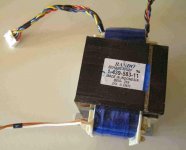
Sounds about right. If there is a part number you could call sonys techline and maybe find out the VA rating?
Hi !
Measured dimension of that transformator.
Maybe we can calculate VA rate(transform in mm ).
Regards zeoN_Rider
Measured dimension of that transformator.
Maybe we can calculate VA rate(transform in mm ).
Regards zeoN_Rider
Actually, what I was wondering about was the voltages - one pair seems too low for a 100 Watt amplifier, the other pair seems way too high.
I was hoping maybe someone had seen one of these before and knew what Sony did with those taps.
I was hoping maybe someone had seen one of these before and knew what Sony did with those taps.
Have a look at these amps
http://sound.westhost.com/project3a.htm 100watt 38vdc
http://sound.westhost.com/project101.htm 180-200 watt 66vdc
http://sound.westhost.com/project3a.htm 100watt 38vdc
http://sound.westhost.com/project101.htm 180-200 watt 66vdc
Thanks for the amplifier recommendations XEagleKeeper, but allow me to drag this back on-topic:
Why are there two sets of taps on the secondary?
Why are there two sets of taps on the secondary?
Probably because the sony required two different supply voltages.Real hard to say without a schematic!Possibly lower voltage for the preamp,flatamps and higher voltage for the poweramps???
Hmmm. +/- 38 VDC is a bit high for a preamp, and I have no idea what a flatamp is (neither does Google 🙂 ). And this is the high current winding - there is a separate low current winding measuring 14-0-14 that is almost certainly for the low-level stuff.
Thanks.
Thanks.
Instead of guessing get a service manual! Flat amp term used to decribe a driver section of a preamp( yamaha's term anyway) as in flat response no coloration of source signal. My yamaha C-4 PREAMP runs a +/- 45vdc so 38vdc is not out of the question.Have you tried a Sony techline.....
Maybe this is crazy, forgive me but somebody told me last year that sony had some models with switching power supply.
A number of AVR's including Sony have a switch on the back labeled 4 0hm vs. 8 ohm. The purpose is to get the user to use lower rail voltages with 4 ohm speakers. This indicates to me either that there are heat dissipation issues with a 4 ohm load or SOAR issues or both.
Such a switch would change which set of windings connect to the rails. I can't say this is the case in the example at hand, but it is a possibility.
Such a switch would change which set of windings connect to the rails. I can't say this is the case in the example at hand, but it is a possibility.
I have a Yamaha HTR5560 that has a similar switch for 8 & 6 ohm combinations. I guess that could also be a possibility.
the higher voltage is for 8 ohm, the lower for 4 ohm and for the surround amps.
60V is correct for a 100W/8r amp (44*1.414=62) and 38V is about right for 100W/4r.
60V is correct for a 100W/8r amp (44*1.414=62) and 38V is about right for 100W/4r.
Thanks, UncleJed. That sounds good, except that's a 44-0-44 winding (88 VCT), which would give a +/- 62 VDC supply, which would be more like 240 Watts into 8 ohms. Oh, well, I'll find a use for it.
- Status
- Not open for further replies.
- Home
- Amplifiers
- Solid State
- Transformer from Sony A/V Receiver - what's up with these windings?