You have to test a single ended transformer with the same conditions that it will be used (or in the same reverse conditions that it will be used ).
You do not drive a 5k primary with a plate impedance, rp, of 5k, because:
The damping factor will be very low, only 1.0; the low frequency bandwidth will be very limited by the primary inductance; and the high frequency bandwidth will be very limited by the primary distributed capacitance.
And, driving the 8 Ohm secondary with 8 Ohms will also give a low damping factor of 1.0, and will limit the low and high frequency responses at the 5k primary.
But you are correct, when you test the 5k to 8 Ohm transformer in reverse, you do load the primary with 5k Ohms.
Instead, for example, you drive the 5k primary with a plate impedance, rp, of 1.25k Ohms. That gives a damping factor of 4.0; and the low frequency bandwidth goes 4 times lower, and the high frequency bandwidth goes 4 times higher; versus driving it with 5k Ohms.
And you load the 8 Ohm secondary tap with 8 Ohms.
Suppose you want to test by using the reverse method:
So you drive the 8 Ohm secondary with 2 Ohms, and load the primary with 5k Ohms. That gives the same damping factor of 4.0, and the low frequency bandwidth and high frequency bandwidth are extended.
A transformer needs the drive impedance and the load impedance to give the proper damping factor and low and high frequency bandwidths.
Example, 1000pF distributed capacitance on the 5k primary, on the secondary will be multiplied by the turns ratio.
5k to 8 Ohms = 25:1 turns ratio. 500pF x 25 = 25,000pF at the secondary.
Of course there are many other factors that affect the transformer's performance, such as:
Leakage reactance, primary DCR, secondary DCR, lamination saturation, etc.
Please try to test really with revers method as described in other thread; you will find that is a very good method that can give you all the information you need.
I have shown the frequency answer with a standard metho ( very limited) and reverse metohd and the curves are perfectly similar; of course the standard method can't have the same swing, same Zout and frequency answer that the reverse mode has.
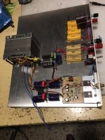
Regarding the dc current I hope to explain soon the proto I made .
In attach the photo
Attachments
One more consideration
About simulations.
In which way I can simulate an OT trafo when each one is different from others?
It isn't the right way to understand the real OT we have to use.
Unfortunately to do the best test you have to spend money.
Walter
About simulations.
In which way I can simulate an OT trafo when each one is different from others?
It isn't the right way to understand the real OT we have to use.
Unfortunately to do the best test you have to spend money.
Walter
Simulation, Simulation?
Often not possible to do a realistic simulation.
Spend money ($pend money)?
No . . .
Test equipment is not cheap.
Amplifier parts are not cheap.
There is another method that does not require either testing output transformers, or building an amplifier to test/listen.
Just do enough reading of the Tubes / Valves threads, and you will get a flavor of what amplifiers (and with what loudspeakers)
sound pleasing to multiple Post-ers.
Sometimes you have to do some things on faith.
Warning: It is true, there are some post-ers will never be satisfied with any combination of amplifiers and loudspeakers.
Wanting to improve your system is one thing, but if you never can enjoy listening, just stop listening.
Just my opinions
There is a good Crowhurst article about transformer distortion. It's basic points are:
1. At high frequencies, transformer distortion is negligible.
2. At low frequencies, core saturation is the major cause of distortion. Saturation distortion is caused by insufficient primary inductance for a given frequency and voltage input.
3. With zero source impedance, there is no transformer distortion. If source impedance is more than zero, intrinsically non-linear magnetizing current passing through the source causes voltage waveform distortion.
4. For a given frequency, higher primary inductance results in less magnetizing current, hence less distortion.
Not discussed in the Crowhurst article is effect of hysteresis, which contributes to non-linearity of magnetizing current. Ferromagnetics with high hysteresis cause more distortion than those with low hysteresis.
Once you have basic understanding of transformer distortion, you will learn how to minimize it, and stop worrying.
Attachments
Simulation, Simulation?
Often not possible to do a realistic simulation.
Spend money ($pend money)?
No . . .
Test equipment is not cheap.
Amplifier parts are not cheap.
There is another method that does not require either testing output transformers, or building an amplifier to test/listen.
Just do enough reading of the Tubes / Valves threads, and you will get a flavor of what amplifiers (and with what loudspeakers)
sound pleasing to multiple Post-ers.
Sometimes you have to do some things on faith.
Warning: It is true, there are some post-ers will never be satisfied with any combination of amplifiers and loudspeakers.
Wanting to improve your system is one thing, but if you never can enjoy listening, just stop listening.
Just my opinions
The only way to get an information around OT is to test in the real world the stuff from different source, possibly with reverse mode and a minimum of test set up ( as described)
The satisfaction is directly related to the background who everyone has and the approach with the technical aspect
Walter
point nr.2The only way to get an information around OT is to test in the real world the stuff from different source, possibly with reverse mode and a minimum of test set up ( as described)
The satisfaction is directly related to the background who everyone has and the approach with the technical aspect
Walter
There is also a distortion from tubes that must give more current in a non linear region due the drop of inductance
But if you don't know which is the limit of one certain OT you can't understand the weight of the tube around this issue
Walter
I love point 3:
"With zero source impedance, there is no transformer distortion. If source impedance is more than zero, intrinsically non-linear magnetizing current passing through the source causes voltage waveform distortion.
Walt, did you read that? Think again about your serie resistor.......
"With zero source impedance, there is no transformer distortion. If source impedance is more than zero, intrinsically non-linear magnetizing current passing through the source causes voltage waveform distortion.
Walt, did you read that? Think again about your serie resistor.......
That means your idea "measuring the transformers distortion" with your suggested set-up was wrong from the start and the frequency respons as Timmert already proved too.Hi
I can't help you, sorry.
Walter
Trolling post?I love point 3:
"With zero source impedance, there is no transformer distortion. If source impedance is more than zero, intrinsically non-linear magnetizing current passing through the source causes voltage waveform distortion.
Walt, did you read that? Think again about your serie resistor.......
Note the most important word/s - non linear.
A straight resistor is linear.
So you now should realise you were talking Garbage.

Another consideration.
At that time the possibility to have a test set was not easy as now.
A good ss amp wasn't available; so now you can drive a secondary trhough the resistor in a best way if the amp is good enough.
Also with a good sound card and a sw you can see a lot of information of the OT alone, outside from circuit.
Walter
I often test the transformer at low levels. And then I just install it in a real amplifier and test it again, exactly as it will be used.
In general, many of the characteristics will neither change nor get better when you test it at high levels.
Examples:
DCR, unless it heats up under the quiescent DC current in a more complete test.
'Turns' Ratio (if that changed, then old electronic engineers would 'turn' over in their graves).
Leakage Reactance from the primary to the secondary.
You should be able to do a little thinking, and find other characteristics that do not change from the low level test, versus the high level test.
(hint: what are the factors of insertion loss, at levels lower than the saturation level).
Think of some more.
Just my opinions.
How about if you measured driving backwards in situ - let the output tubes themselves load the "secondary" via their idle current? You'd have to pull the phase splitter tube, so it's just the output tube and their bias current of course.
Might be a trick to get across the secondary with each end sitting at ~400V above ground with your sound card. You'd have to build a HV diff probe with even less distortion...
I suppose that would account for any DC current offset in a P-P output, unless the amp has perfect bias balance, which most ordinary units do not. Also who's to say equal currents in each primary winding about the center tap yields perfectly balanced magnetic flux in the transformer core? The transformer winding construction is that good? Maybe...
One could always drive the transformer backwards and simply listen to the sound on the other side - perhaps with a circuit that places a little DC offset to account for imperfect balance when actually used. Do two transformers, in stereo, with headphones AC coupled...
I was doing that for a while in doing HiZ (current) speaker drive, using transformers to change a voltage output into a current.
A normal amplfier is also linear with different loads. So who is trolling? You didn't understand what Norman Crowhurst ment?Trolling post?
Note the most important word/s - non linear.
A straight resistor is linear.
So you now should realise you were talking Garbage.
A transformer can be evaluated for its non-linearity using a zero-impedance source (and preferably without a load, to avoid the dilution of the THD), but you simply have to measure the distortion in the magnetising current; another way of rephrasing what Crownhurst said decades ago and still perfectly makes sense today,
He means ZERO!! Not even winding resistance!!good Crowhurst article about transformer distortion. .....
3. With zero source impedance, there is no transformer distortion.
This is difficult in practice. There are several circuits to do it, but they tend to get out of balance with temperature change (coefficient of temperature of winding).
A different scheme, for INputs, is a zero Ohm load. An opamp virtual ground.
There are superconductors😎He means ZERO!! Not even winding resistance!!
This is difficult in practice. There are several circuits to do it, but they tend to get out of balance with temperature change (coefficient of temperature of winding).
A different scheme, for INputs, is a zero Ohm load. An opamp virtual ground.
Norman also say a good transformer has 95% efficiency, about 0,2 dB loss. That means that probably 95% from all SE transformers are not good enough, maybe even more. Really nice guy.
I often test the transformer at low levels. And then I just install it in a real amplifier and test it again, exactly as it will be used.
In general, many of the characteristics will neither change nor get better when you test it at high levels.
Examples:
DCR, unless it heats up under the quiescent DC current in a more complete test.
'Turns' Ratio (if that changed, then old electronic engineers would 'turn' over in their graves).
Leakage Reactance from the primary to the secondary.
You should be able to do a little thinking, and find other characteristics that do not change from the low level test, versus the high level test.
(hint: what are the factors of insertion loss, at levels lower than the saturation level).
Think of some more.
Just my opinions.
As wrote in another thread, if you want to understand what happen at 1 watt on 8 ohm as out power you need 2,7 volt rms on it; it is not high level. It is an example.
If you have a OT with 30:1 pp you must delivery 81 Vrms at the end primary of OT.
In which way you can see in which way the OT itself works?
Which generator can develop that voltage, with a proper Zout similar to effective Rp of tubes and low distortion?
And we are speaking of only 2,7 volt/8 ohm
Because , for me, is not important to see the spec of OT with Zout=0, is not on the real world.
And sure not at +/- 80 mV!!!!
My point of view
No Walt, what you are saying is nonsens, other signals are perfectly allowed as long there is no saturation and not to low to have problems with noise or hysteresis.As wrote in another thread, if you want to understand what happen at 1 watt on 8 ohm as out power you need 2,7 volt rms on it; it is not high level. It is an example.
If you have a OT with 30:1 pp you must delivery 81 Vrms at the end primary of OT.
In which way you can see in which way the OT itself works?
Which generator can develop that voltage, with a proper Zout similar to effective Rp of tubes and low distortion?
And we are speaking of only 2,7 volt/8 ohm
Because , for me, is not important to see the spec of OT with Zout=0, is not on the real world.
And sure not at +/- 80 mV!!!!
My point of view
And my input signal was not +/- 80mV that was 20 times bigger. I also explained that i also used even much bigger signals up to 30V sqw. and that the outcome was almost 100% the same. Learn to read! And start with good literature as N.Crowhurst.
- Home
- Amplifiers
- Tubes / Valves
- Transformer distortion (THD)