ifi claims to be 20 times better on the noise front (1uV vs 20uV) than a LPS - "in the audio band".
And then they exclude mains frequencies and switching frequency (<30uV!!!) from that statement. All that is nothing but a bad joke. 🙄
Another question is whether that's the only thing that really matters or matters the most, which is what you asked earlier.
Not really, it's a general thing.
The issue is general. The way of how to cope with it makes the difference!
And that depends on each device.
###
Your "grounding" arguments don't convince me.
How much and which type of current flows in the ground inside your system
depends on your grounding scheme.
Getting that straight is a major key to success. You need to picture the current path for each and every part of your system.
If you find all the crap on your RCA signal ground, for sure you havn't done your homework.
Not sure what's your RPI talk is all about.
E.g. Things like isolating your system from a network ground I consider common
knowledge. 3 simple options come to mind: No cable shield. Fiber. WLAN.
Your "grounding" arguments don't convince me.
Feel free to believe otherwise.
LT3042 and LT3045
Just small update what it is in preparation.
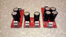
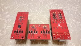
1. Dual 200mA LT3042 PCB
2. 2x LT3042 400mA with CRC filter
3. 6x LT3045 high current output 3A board
These PCB will be ready at the end of next week. Stay tuned for update😉.
Just small update what it is in preparation.
1. Dual 200mA LT3042 PCB
2. 2x LT3042 400mA with CRC filter
3. 6x LT3045 high current output 3A board
These PCB will be ready at the end of next week. Stay tuned for update😉.
Attachments
Just small update what it is in preparation.
1. Dual 200mA LT3042 PCB
2. 2x LT3042 400mA with CRC filter
3. 6x LT3045 high current output 3A board
These PCB will be ready at the end of next week. Stay tuned for update😉.
Interesting, what output voltages?
Ales.
Looks great. 😀
I guess standard voltages will be 5V/3.3V -- right?
If I'd need e.g. 3.6V for the Sabre, I'd have to change a resistor on board - correct??
Looks great. 😀
I guess standard voltages will be 5V/3.3V -- right?
If I'd need e.g. 3.6V for the Sabre, I'd have to change a resistor on board - correct??
@Studley & soundcheck: There will be most common voltages such as 3.3V, 5V, 12V. Other output voltages are also possible by changing set resistor.
@Theodosis: You can always connect two outputs together to get let say +/-12V or you can reverse voltage , but in last case own transformer is a must and ground must not be connected to common ground.
Best Regards,
Aleš
@Theodosis: You can always connect two outputs together to get let say +/-12V or you can reverse voltage , but in last case own transformer is a must and ground must not be connected to common ground.
Best Regards,
Aleš
I once more had a look at the new boards .
Some comments/ideas that popped up.
1.
Did you leave out the holes after the rectifier on purpose?
To me these made sense if I want to bypass the rectifier and solder wires right to the board.
2.
I see a common mode choke just on one board. Hmmh. Why is that?
3.
Beside that, I see that you pretty much removed all other filtering stuff known from the TPS7A4700.
No way to add some small Wimas or similar anymore !?!?
4.
Why do you suddenly use the ground plane as ground after the 2nd buffer cap?
Wouldn't it be better to keep the trace shape symmetric towards the LT3042 ?
Similar questions I have when looking at the output. Why using the ground plane?
But hey. I'm not a board designer. Just read this or that application note from this or that device.
5.
Would be nice to have some additional holes at the Rset.
This would make live much easier to introduce all kind of resistors for setting the voltage.
Especially sourcing high-quality throughhole resistors is much easier.
E.g I'd have to use two Rs (e.g. Vishay-Dale CMF55-143 20&16,2k) in series to achieve the 36k for e.g. 3.6V out.
People for sure will have to play with different R combinations to achieve this or that voltage.
You might consider this on the layout.
6.
From what I know, there is this "capacity/10" rule when paralleling caps for power supplies. You always seem to use equally sized caps.
Any pros and cons?
7.
I don't know how other people see it. I would like to see the terminals
out by default to avoid associated parasitics. At these quality levels everything counts.
You can just put them in the bag. People can solder them in - if they like - later on.
Anything else? Hmmh. For the moment I ran out of questions/ideas 😀
Cheers
Last edited:
Just to follow up on my comments.
By coincidence I stepped over a Salas LDO board image.
It seems they are not using the groundplane as common ground.
Interesting.
I think people want a clean/defined return path.
And also separate the buffer cap charging section (input/high current section)
from the rest (low-current) of the board.
I don't know how much impact all this might have.
I once more had a look at the new boards .
Some comments/ideas that popped up.
1.
Did you leave out the holes after the rectifier on purpose?
To me these made sense if I want to bypass the rectifier and solder wires right to the board.
2.
I see a common mode choke just on one board. Hmmh. Why is that?
3.
Beside that, I see that you pretty much removed all other filtering stuff known from the TPS7A4700.
No way to add some small Wimas or similar anymore !?!?
4.
Why do you suddenly use the ground plane as ground after the 2nd buffer cap?
Wouldn't it be better to keep the trace shape symmetric towards the LT3042 ?
Similar questions I have when looking at the output. Why using the ground plane?
But hey. I'm not a board designer. Just read this or that application note from this or that device.
5.
Would be nice to have some additional holes at the Rset.
This would make live much easier to introduce all kind of resistors for setting the voltage.
Especially sourcing high-quality throughhole resistors is much easier.
E.g I'd have to use two Rs (e.g. Vishay-Dale CMF55-143 20&16,2k) in series to achieve the 36k for e.g. 3.6V out.
People for sure will have to play with different R combinations to achieve this or that voltage.
You might consider this on the layout.
6.
From what I know, there is this "capacity/10" rule when paralleling caps for power supplies. You always seem to use equally sized caps.
Any pros and cons?
7.
I don't know how other people see it. I would like to see the terminals
out by default to avoid associated parasitics. At these quality levels everything counts.
You can just put them in the bag. People can solder them in - if they like - later on.
Anything else? Hmmh. For the moment I ran out of questions/ideas 😀
Cheers
1. Yes, you can connect DC before diodes. On the 400mA version there is also marking on the PCB.
2. It is because of price reduction and not every board has the same purpose.
3. I don't quite understand what filtering do you mean? To fit some bypass caps over diodes? If that is the case you can still do that and solder caps directly on the diodes. Now there is more space between them.
4. There is GND ground plane on both sides of the 400mA PCB. It helps to spread the heat evenly across PCB and better sink function. I try to avoid those heatsinks, as folks really know how to make a mess with them.
5. This resistor is critical for performance of the LT3042 and LT3045. So inserting through hole resistor is bad idea. Long leads will just bring noise into the circuit. I am sure that almost every electronic store has 1% 0805 resistors for every common voltage setting.
6. Can you point me to this rule? Anyway there are always smaller capacitors after big ones. TPS7A4700 has 47uF tantalum to avoid ringing from SMPS, but a lot of folks are afraid to use SMPS in audio, so it is a bit of waste. I excluded it from LT3042 PCBs to reduce price and also because LT3042 performs worse than TPS7A4700 when it comes to SMPS.
7. Pictures attached were for reference only. When PCBs will be shipped, big capacitors and connectors will not be soldered into the PCB.
Just to follow up on my comments.
By coincidence I stepped over a Salas LDO board image.
It seems they are not using the groundplane as common ground.
Interesting.
I think people want a clean/defined return path.
And also separate the buffer cap charging section (input/high current section)
from the rest (low-current) of the board.
I don't know how much impact all this might have.
Unfortunately most of us are lacking some serious measuring equipment to evaluate such case.
Best regards,
Aleš
1.
Diodes add their own parasitics and cause a voltage drop. That's not necessarily a good thing.
Especially if you feed DC only.
And. Why is just the 400mA version different? You had it right on the TPS!?!?
2.
Price reduction?? Come on. People who buy your devices look pretty much for no compromise solutions.
Why going up a step up with the LT3042 and then several steps
down on the peripherals. That doesn't make any sense to me.
The boards differ only in the current capabilities? I'd expect the very same layout for all of them.
What does a "different purpose"has to do with it!?!?
Except you want to cut cost again.
3.
You had taken provisions for additional capacitors in the past.
Beside that.
Do you still have ferrite beads in place to fight e.g. spikes ??
4.
Using a large area, which might be the RF shield, as heatsink is IMO OK.
But it shouldn't interfere with (temperature) sensitive (ground) pins.
The IMO probably best approach would be to have ground traces in place
and to keep the shield/heatsink separate.
Different currents, noise, temperatures (causing noise again) etc. shouldn't be mixed up.
Obviously all different grounds would have to be stargrounded at the optimum spot.
And again. I'd apply the same structure to all boards!
5.
I very well understand that the SET/Vref resistor is most critical.
Therefore it's even more important to have an option to play around with
boutique resistors. And not to go for a 5ct junk resistor ( especially if these
face severe temperature conditions) .
Since you're on the cost saving path, I wouldn't expect a 2.5$ Vishay MELF
or similar at that spot making it into your BOM.
6.
I can't find the reference. But usually it's recommended to have e.g. 4700/470/47 in power supplies.
*******************************
Yep. Measurements are difficult at these levels - I know.
More advanced inmates simulate their designs.
And then there are theoretical aspects, application notes and experiences.
Yep. All that has to be brought together. Live it's not easy. 😉
Please don't consider my feedback as criticism or bashing - I try to be rather constructive. 😀
I'm happily running your old TPS devices.
I just have the feeling that you're going
a.) one step forward and two steps back here
and
b.) that the different boards differ resp. are not consistent for IMO no obvious reason. Basically I'd have to buy the 400mA model to have all filtering and options in place even at a 30mA load. That doesn't makes sense to me.
Cheers
Last edited:
Sorry for late reply. I had flu but I'm all better now.
So a lot of your questions really do get deep into all of the topics so I'd rather leave them there as I do not plan to reveal everything. I try to hear and realize all the requests I get from users, but it is hard to get all into one PCB design. To fit personal taste of everyone it would mean personalized PCB for everyone, and in production that is just a no go.
Still I would like to thank you for your observations and comments.
Best regards,
Aleš
1.
Diodes add their own parasitics and cause a voltage drop. That's not necessarily a good thing.
Especially if you feed DC only.
And. Why is just the 400mA version different? You had it right on the TPS!?!?
2.
Price reduction?? Come on. People who buy your devices look pretty much for no compromise solutions.
Why going up a step up with the LT3042 and then several steps
down on the peripherals. That doesn't make any sense to me.
The boards differ only in the current capabilities? I'd expect the very same layout for all of them.
What does a "different purpose"has to do with it!?!?
Except you want to cut cost again.
3.
You had taken provisions for additional capacitors in the past.
Beside that.
Do you still have ferrite beads in place to fight e.g. spikes ??
4.
Using a large area, which might be the RF shield, as heatsink is IMO OK.
But it shouldn't interfere with (temperature) sensitive (ground) pins.
The IMO probably best approach would be to have ground traces in place
and to keep the shield/heatsink separate.
Different currents, noise, temperatures (causing noise again) etc. shouldn't be mixed up.
Obviously all different grounds would have to be stargrounded at the optimum spot.
And again. I'd apply the same structure to all boards!
5.
I very well understand that the SET/Vref resistor is most critical.
Therefore it's even more important to have an option to play around with
boutique resistors. And not to go for a 5ct junk resistor ( especially if these
face severe temperature conditions) .
Since you're on the cost saving path, I wouldn't expect a 2.5$ Vishay MELF
or similar at that spot making it into your BOM.
6.
I can't find the reference. But usually it's recommended to have e.g. 4700/470/47 in power supplies.
*******************************
Yep. Measurements are difficult at these levels - I know.
More advanced inmates simulate their designs.
And then there are theoretical aspects, application notes and experiences.
Yep. All that has to be brought together. Live it's not easy. 😉
Please don't consider my feedback as criticism or bashing - I try to be rather constructive. 😀
I'm happily running your old TPS devices.
I just have the feeling that you're going
a.) one step forward and two steps back here
and
b.) that the different boards differ resp. are not consistent for IMO no obvious reason. Basically I'd have to buy the 400mA model to have all filtering and options in place even at a 30mA load. That doesn't makes sense to me.
Cheers
Hi, just received my 2 sets of TPS7A4700, there are 2 pieces of small metal bar included, believe to be heatsink, how to attach it to the board?
Hi, just received my 2 sets of TPS7A4700, there are 2 pieces of small metal bar included, believe to be heatsink, how to attach it to the board?
Thos aluminum blocks have double sided thermal adhesive tape. You need to peel off blue protective layer/tape and then just press it against PCB in between two white slotted lines. This thermal tape also acts as insulator so don't worry about shorting anything.
BR,
Aleš
I finished 2 boards, one is fine, but can't get output from another, after check carefully I found one side of 4 diodes were not soldered. (see pic below), it works after I soldered them
Hi Albrerta,
nice to hear that you managed to find the error and fix it. I apologize that I missed that PCB out. Now I will double check.
Best Regards,
Aleš
Hello Àles,
Could you please tell me what is the size and capacitance value of the two ceramic caps at the output of your new LT3042 reg ?
Could you please tell me what is the size and capacitance value of the two ceramic caps at the output of your new LT3042 reg ?
Hello Àles,
Could you please tell me what is the size and capacitance value of the two ceramic caps at the output of your new LT3042 reg ?
Hello Eldam,
Capacitors are 10uF 25V X7R 1206 .
Br,
Aleš
- Home
- Vendor's Bazaar
- TPS7A4700 low noise LDO regulator PCB