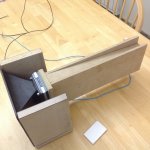
I've come across numerous comments about how much better results were achieved by removing the TPL plastic back cover and replacing it with a 1 to 2 liter chamber that I decided to try it. Build is not the nicest as it is a quick prototype to get some measurements, but functionally it's fine.
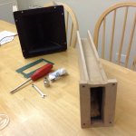
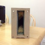
It's a sealed box, 1.3 liters, with paralel vertical walls and sloped top and bottom, internally covered with acoustic barrier and with some fiberglass wool inside, mostly towards the back.
For whatever reason I cannot upload more than one picture to this site from my iPad, so I'll post more pictures and measuremnts on next posts.
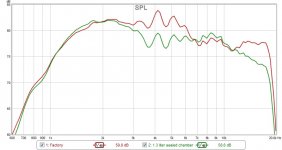
Bottom line: the large chamber is not improving bottom end but has had an impact around 4-5kHz, and the sealed vs open back versions measured identical.
Looking forward to your feedback.
It's a sealed box, 1.3 liters, with paralel vertical walls and sloped top and bottom, internally covered with acoustic barrier and with some fiberglass wool inside, mostly towards the back.
For whatever reason I cannot upload more than one picture to this site from my iPad, so I'll post more pictures and measuremnts on next posts.
Bottom line: the large chamber is not improving bottom end but has had an impact around 4-5kHz, and the sealed vs open back versions measured identical.
Looking forward to your feedback.
Attachments
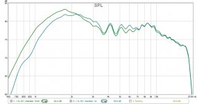
And here are the frequency responses.
I was expecting the unit with the DIY chamber to reach lower, but that is not the case.
Note the vertical axis is significantly expanded, so the variations appear to be larger than what they actually are. Yet starting at 3kHz there is a material difference in response.
The drop at higher frequencies is puzzling.
Does this look like the improvements others have gotten from this mod?
Should I try a different shape chamber?
BTW, I didn't even graphed the response for the DIY chamber without the back because it was identical to the sealed response.
Attachments
A large open volume behind the AMT with thin on-wall absorption material, smoothly merged with a well stuffed exponential tapered volume is the most common simulation model.
Maybe...extend a large rear rectangle a few inches, and then attach a taper(pyramid) behind with stuffing. The rear energy freely expands into a large volume before the rear tapered volume removes resonances. No early "restrictions" reflecting back to the thin AMT membrane.
Maybe...extend a large rear rectangle a few inches, and then attach a taper(pyramid) behind with stuffing. The rear energy freely expands into a large volume before the rear tapered volume removes resonances. No early "restrictions" reflecting back to the thin AMT membrane.

Neither did mine.the 2 units that i measured, didnt have that peak with standard chamber.
Thought I'd try to fit them for comparison, if it helps.the 2 units that i measured,
Attachments
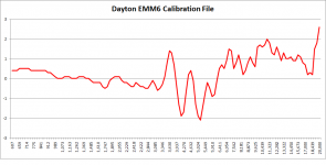
Thanks for the feedback! Your comments made me wonder about the mic, so I plotted the calibration file that came with it. See below.
Would you agree the peaks around 4kHz are likely related to the mic or its calibration file?
If so...maybe I should a) look into having the mic calibrated, and b) not worry too much about what is showing up in absolute terms and rather focus now on the relative responses with and without the stock chamber.
Attachments
You could make some tries to see how move your curve:
If you fill the cabinet with hard wood : you can reduce the volume
if you fill the cabinet with more 50% of wools to 100% yo can rise artificialy the cabinet volume by around 20% (around ?)
From there maybe the pros should be easieler answer about the mic, the cabinet, etc
two cents, but fast to do !
Strange calibration file, but scale is making these to look a bit strange. Those wiggles near 4kHz are clearly some resonances of mic head or capsule.
Another thing - how is measurement taken? At what distance? How was speaker mounted?
Another thing - how is measurement taken? At what distance? How was speaker mounted?
Strange calibration file, but scale is making these to look a bit strange. Those wiggles near 4kHz are clearly some resonances of mic head or capsule.
Another thing - how is measurement taken? At what distance? How was speaker mounted?
Too bad I didn't take pictures of the measurement setup. But it was at 1m distance from mic to horn mouth, on axis. TPL was sitting on a ladder, about 75cm from floor (with thick wool carpet). And 2+ meters to all other walls.
Measured with REW with frequency dependent windowing set at 5 cycles.
I think that you should measure this kind of things in nearfield, right at horn opening level or only some cms away. 1m away shows too much interferences from outer space!
I think that you should measure this kind of things in nearfield, right at horn opening level or only some cms away. 1m away shows too much interferences from outer space!
OK. I re-did the measurements. This time on-axis, 15cm away from the mouth. I intended to take measurements closer to the mouth but the soundcard I use for measuring is a bit noisy and if I had the mic closer a gain loopback developed.
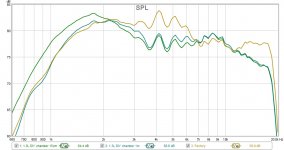
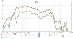
Attached is a shot comparing the DIY chamber unit taken at 1m vs 15cm, both with FDW at 5 cycles. I think they are basically the same, except for the lower end.
Another shot comparing factory at 1m, DIY chamber at 1m, DIY at 15cm.
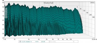
And waterfall charts of the factory and DIY chamber versions, both taken at 1m. There is some improvement with the DIY chamber, but I wonder how material this is. I was hoping to see the resonance Lgrau and others have reported around 1.8kHz, but I can't see them.
I tried looking at distortion, but the differences were negligible.
Maybe I should try a wider DIY chamber. The current one is 3.8cm wide, same as the TPL opennings. And 3.8cm is about 4kHz wavelength...
Attachments

It looks that way.. try it on another tweeter. Try it both facing the driver and perpendicular to it (are there instructions with the .cal file?)Would you agree the peaks around 4kHz are likely related to the mic or its calibration file?
In my own experiences (for what it's worth) wiggles in the files may expose themselves as false calibrations after you've taken enough measurements and keep finding them in the response plots.
It looks that way.. try it on another tweeter. Try it both facing the driver and perpendicular to it (are there instructions with the .cal file?)
In my own experiences (for what it's worth) wiggles in the files may expose themselves as false calibrations after you've taken enough measurements and keep finding them in the response plots.
I think we can see the same wiggles at 4 to 5kHz in these other measurements of a Faital M5N12 in a prototype horn. Sorry the graph is busy, but it is what I had available on this work laptop. I have REW on another laptop.
So it looks like it's the mic/cal file introducing the wiggles.
Your comment made me wonder about the cal file itself. Was it a calibration made with the mic sitting vertically or horizontally to the axis? I don't know. Nothing in the instructions. I have used it horizontally, aligned with the axis. Will try it perpendicular to the axis.
Yet, can we draw any cconclusions about the impact of the DIY chamber based on the relative changes between curves with stock and DIY chambers?
Attachments
A large open volume behind the AMT with thin on-wall absorption material, smoothly merged with a well stuffed exponential tapered volume is the most common simulation model.
Maybe...extend a large rear rectangle a few inches, and then attach a taper(pyramid) behind with stuffing. The rear energy freely expands into a large volume before the rear tapered volume removes resonances. No early "restrictions" reflecting back to the thin AMT membrane.
I'll likely go down this road. Not sure at this point if I'm expecting much in terms of audible difference, though.
Extending the rear rectangle 5cm to the back, then tapering to a 12cm truncated pyramid ending on a 5x5cm square yields a volume of 1.5 liters. It seems to make sense...but I would love to see some measured evidence that I'm on a good path.
A peak could be the soil or ceilling. But a huge deep ???
Did the mic fall on a floor ? (children, dog...) capsule good at eyes ?
You can try also for checking the mic with and w/o calib file by measuring the TP without is H from above (TPL AMT semi-digged on the garden ground (if one has its genuine back plate yet !)
My two cents +
PS : is a minimum delay needed outside ? (when not at 50 feets from solid surface but the ground )
Last edited:
- Home
- Loudspeakers
- Multi-Way
- TPL-150H back chamber mods