Ok. this isnt a SQ mod.. i have none of the skills necessary for suggesting one of those. .
however, i have a case which i would like to mount two of these boards in, but its not quite tall enough ( i dont think, still trying to find out total height of evaluation board).
i will however be removing the heatsinks and have alu plate in place of it, which will be mounted to the extruded heatsink on the side of the case.
looking at the few photos and the documentation, it -seems- that with the heatsink removed, the big rear capacitors would fit on the front face of the board, drastically reducing its height.
could anybody already in possession of the board give it a quick look over.. would the big capacitors fit on the front face? it looks like they would be quite tight with the inductors there..
alternatively i could swap them for slimmer, taller caps, also mounted on the front.
Are those capacitors on the signal path? or are they power related? would mouting them on a daughterboard connected with short (circa 8-10cm) , fat wires cause problems?
ok so thats 7.7 cm. my case has an internal height of 6.2 cm.. so unless there is a variant of my suggested mod which could work, either choose a diff amp, or get a new case. i do like the case tho 🙂
http://www.audiophonics.fr/11211-th...m-diy-box-case-with-heatsink-320x248x70mm.jpg
http://www.audiophonics.fr/11211-th...m-diy-box-case-with-heatsink-320x248x70mm.jpg
Maybe you replace that heatsink by some flat cpu-cooler.
Removing the big caps to another place is not advisable at all.
Removing the big caps to another place is not advisable at all.
yes i realised that its a very bad idea to place them further from the chip (reading lots last night!)
however i still think placing them on the opposite side of the board should be ok...? distances will remain the same..
from what i can see the heatsink is the only thing blocking them from being on that side anyway, nd i plan to replace that. although id need somebody with the board to confirm this, as they *might* hit the inductors there.. looks close.
i have no idea as to the sensitivity to placement and distance we are discussing here though.. i know they need to be as close as possible to output of chip. would simply extending the legs of the capacitors to allow horizontal mounting (with a slimmer, taller capacitor) have a major bad effect? we would be talking about an extra 1.5 cm of distance in connections in that case.
Last edited:
You want a 4ch amplifier ? And you are talking about the 4 electrolytics one can see from topside ?
no im talking about the two big 4700 uf capacitors on the bottom of the board.
if you look at the photos of the topside of the board, you can see where the pins come thru..
and yes, im planning on running two of these boards for a 4 ch amp.
if you look at the photos of the topside of the board, you can see where the pins come thru..
and yes, im planning on running two of these boards for a 4 ch amp.
If you can find tall thinner capacitors in good quality, then you could bend the pins, and lay the capacitor down. But be aware not to make antennas. A tall capacitor should actually by design have better ESR values! Correct me if I'm wrong
yeah i was just looking into that.. to be honest if theya re on the back of the board, im not sure if it would actually save space.. hard to say without board-in hands, but id imagine a slimmer capacitor in its side, would not be much (if any) lower profile than the current short fat ones on there now..
think only option is topside mounting... or a different amp.
- if it appears they would hit the inductors mounted on the top, i could also use taller slimmer ones, in combination with topside mounting..
but i have an uneasy feeling that im missing some other eason they are on the back.. TI must have had a good reason to do such an awkward design.. seems odd they would do it just due to heaatsink shape.. there are a lot of heatsinks available!
Last edited:
4x of these:
EGPD630ELL242MM40H
EGPD630ELL242MM40H United Chemi-Con | Mouser
The newest latest.
(I'd guess 2 of them would be enough as these are way lower ESR at ~samecurrent capability.)
EGPD630ELL242MM40H
EGPD630ELL242MM40H United Chemi-Con | Mouser
The newest latest.
(I'd guess 2 of them would be enough as these are way lower ESR at ~samecurrent capability.)
Last edited:
ok im going to show my noobishness now (if i didnt already)
would i connect those in parallel to replace the single big one?
do you have an eval board? ive been following your design work, very nice. (and nice renderings - thats my day job)
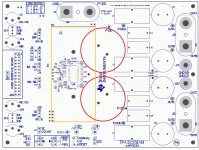
if you have the eval bord, would the existing caps fit on the front if the heatsink was removed? not sure if they would hit inductors L3 and L4..
another alternative, since its you im speaking to, would be your 3255 design.. but i guess id have to build it myself even if i could get the boards from you? (rather beyond my skills i think.. my last diy amp was a gainclone with about 5 components)
would i connect those in parallel to replace the single big one?
do you have an eval board? ive been following your design work, very nice. (and nice renderings - thats my day job)
if you have the eval bord, would the existing caps fit on the front if the heatsink was removed? not sure if they would hit inductors L3 and L4..
another alternative, since its you im speaking to, would be your 3255 design.. but i guess id have to build it myself even if i could get the boards from you? (rather beyond my skills i think.. my last diy amp was a gainclone with about 5 components)
ah i was unsure as in the past ive been told to double capacitance you need 4x capacitors in series/parallel.
yes but those capacitors are much smaller, and the pins are in a different location on the board
if you look in the pdf for the 3255 you can see clearly the pins for the big caps coming thru to the front, they ar also in a different location to those shown in the board schematic in the same document, which, on closer inspection, is the schematic for the 3251, not the 3255. hence i have no way to actually work it out for myself without buying the damn things
if you look in the pdf for the 3255 you can see clearly the pins for the big caps coming thru to the front, they ar also in a different location to those shown in the board schematic in the same document, which, on closer inspection, is the schematic for the 3251, not the 3255. hence i have no way to actually work it out for myself without buying the damn things
The big caps (4700uF) are there for their ESR performance and current capability not so much for their capacitance.
"High voltage" caps with low ESR and high current isn't something every vendor offers. That's why i am saying, you most likely get away with only 2x2400uF due to their excellent ESR/current performance.
They should fit nicely on the top side.
Yes, an eval board is available here. Thanks for the flowers. 🙂
No, it won't fit:

Correct, you would need to build one up for yourself, if boards where available.
"High voltage" caps with low ESR and high current isn't something every vendor offers. That's why i am saying, you most likely get away with only 2x2400uF due to their excellent ESR/current performance.
They should fit nicely on the top side.
do you have an eval board? ive been following your design work, very nice. (and nice renderings - thats my day job)
Yes, an eval board is available here. Thanks for the flowers. 🙂
if you have the eval bord, would the existing caps fit on the front if the heatsink was removed? not sure if they would hit inductors L3 and L4..
No, it won't fit:
another alternative, since its you im speaking to, would be your 3255 design.. but i guess id have to build it myself even if i could get the boards from you? (rather beyond my skills i think.. my last diy amp was a gainclone with about 5 components)
Correct, you would need to build one up for yourself, if boards where available.
Attachments
i am going to pull the trigger and buy these badboys. i will assume i can find a solution to the height issue. either by buying other caps which will fit, or by adding very short horizontal extensions from the solder pads across the top of the board, to shift the big caps sideways until the fit. removing the heatsink will free up a fair amount of space, and i can design my replacement to fit the space i have.
- Status
- Not open for further replies.
- Home
- Amplifiers
- Class D
- tpa3255evm spacesaver mod