In SE mode it should swing close from ground to the + rail when measuring from out A to ground. If in BTL mode you should get nearly 2x the supplyvoltage peak to peak when measuring from out A to outB. Are you sure the post filter feedback is disconnected. Enabling post filter feedback reduces the gain. I'm wondering if the clipping occurs before the chip.
Had to do a recheck, i may need to remove a couple more components in order to remove post filter feedback entirely, however the external buffer is soldered directly onto the input caps for the chip. But by soldering the external buffer to the resistors(2k7) before this cap reduces the gain due post filter feedback being active
On my tpa3255 I tested with 100 ohm loads first. I am using a linear power supply. I wanted to know the maximum RMS voltage output when the power supply is lightly loaded. I then increased the load till 3 ohms. This sort of gave me a crude dynamic range. Try with a high Z load ie 100 Ohms or more.
I can try this tomorrow 🙂
There is a pin on the 3255 that sets the max output current, is that ok?
Yeah, 22k resistor here. Should allow 17A. Tried with 30k to which should allow 13A - No difference
Are you running SE mode or BTL mode?
With 55volt rail and 8 ohms you should get at least 30-32 volts RMS reasonably clean. The switching frequency will show up in your display on top of your sine wave.
Are the bootstrap capacitors ok?
With 55volt rail and 8 ohms you should get at least 30-32 volts RMS reasonably clean. The switching frequency will show up in your display on top of your sine wave.
Are the bootstrap capacitors ok?
Running in BTL mode. Just tried to replace the bootstrap caps with caps from another order. Same same
D
Deleted member 148505
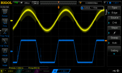
If you can drive the output rail to rail (with the output signal looking square wave-ish), without triggering !fault then your amp is working good.
In the datasheet !clip_otw signal is activated at the onset of clipping (0.01% THD). So clip led already lights up even when the output does not look like it's clipping already.
It has a pulse injector so that the output stage is still switching even on clipping condition.
Can you post scope screenshot?
If you can drive the output rail to rail (with the output signal looking square wave-ish), without triggering !fault then your amp is working good.
In the datasheet !clip_otw signal is activated at the onset of clipping (0.01% THD). So clip led already lights up even when the output does not look like it's clipping already.
It has a pulse injector so that the output stage is still switching even on clipping condition.
Can you post scope screenshot?
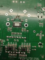
I can drive the board to 44v without triggering !fault. And i have changed my tougths on this, the peaks i hear when playing music may very well come due to incorrect capacitor on VBG(error on my PCB vs. Latest drawing, apparently i have updated some components there after board went into production - mixup is between C24-C26) - Check out IMG_20210206_171233, i have managed to place an 100p C0G here..
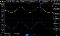
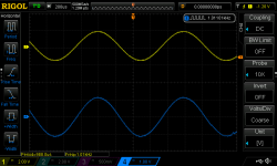
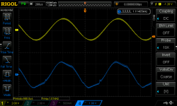
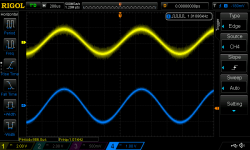
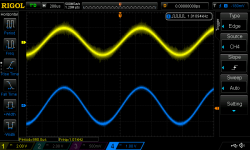
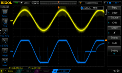
Attached is averages from scope. QuickPrint2 is on 23v output, Quickprint3 is on 26v output, and slightly dimmed clip_otw, QuickPrint4 is on 33v output and clip_otw is more or less on.
Blue line is output from SC FFT Analyser, Yellow line is output from Akitika 1khz oscillator before gain buffer.
Attachments
Last edited:
Attached here is highres output from scope. QuickPrint6 is with 23v output(No clipping detected), QuickPrint7 is with 26v output and slight dimmed clip_otw, QuickPrint9 is with ~33v on output with clip_otw on and QuickPrint11 is with ~43v on output with clip_otw on.
Will do a "live" test with 100n on VBG, i was not able to detect change on the scope.
Outputs is connected to scope through SC FFT Analyser i bought from you, Lester
Blue line is output from SC FFT Analyser, Yellow line is output from Akitika 1khz oscillator before gain buffer.
Will do a "live" test with 100n on VBG, i was not able to detect change on the scope.
Outputs is connected to scope through SC FFT Analyser i bought from you, Lester
Blue line is output from SC FFT Analyser, Yellow line is output from Akitika 1khz oscillator before gain buffer.
Attachments
Last edited:
- Home
- Amplifiers
- Class D
- TPA3255 Troubleshooting