I use this one.
The difference in the price / quality ratio.
You get 4 BTL channels for the price of two.
But, I immediately replaced the TL 071.
It is possible to switch to 1PBTL + 2BTL mode.
I have three speakers in each speaker. I connect the PBTL channel at the low frequency, and at the midrange and high frequencies through the BTL channel.
It is not recommended to use a power supply with a voltage higher than 36 volts.
On your first link, a similar amplifier, only on TPA 3251
It will heat up less because it has a better radiator.
The rest I don't know, newer developments.
The only real advantage is the price.
Thanks Polevka,
Are you happy with the sound quality and overall performance of this board ?
Do I understand correctly - you use one board per speaker cabinet, 2 channels combined (PBTL) for bass and 1 each BTL (as delivered) for mid and tweeter ?
There is a DIS-advantage to using the 4-channel boards: the heatsinks are too small. Even with the 4ch board designed by 3e-audio, he cautions against using the full TPA3251 rail voltage with 4 Ohm loads. It's because too much heat will be generated, especially if the amp board is enclosed in a box without forced air (fan) cooling added.
I have a 4-ch TPA3255 board and I am thinking of making an aluminum spacer block to replace the existing heatsink. I can then mount the board via the spacer block to a larger heatsinnk.
As long as the PCB traces can handle the necessary current flow, there is nothing technically wrong with these 4-ch boards. Well, as long as they are designed correctly and the layout is good. But it is difficult to know that without buying and measuring one!
Thanks Charlie
Are you happy with the overall outcome of the board you have (is it one of those I listed ?). Did you have to make many modifications to achieve acceptable performance ?
Since I'm only looking for 2 way active speakers I could go with 2 stereo boards in a single case (or even separate cases) but I have wondered about power / volume coordination across multiple boards. The 3E stereo boards offer "master/slave" linking and I wondered whether or not it's effective/worthwhile
Note that one of the variants I linked offers up to 8 channels on a single board. That variant uses fans ie. forced cooling though I cannot see any details of the fan control / noise - the "cure" may be worse than the "problem"
Each speaker has one board.Thanks Polevka,
Are you happy with the sound quality and overall performance of this board ?
Do I understand correctly - you use one board per speaker cabinet, 2 channels combined (PBTL) for bass and 1 each BTL (as delivered) for mid and tweeter ?
PBTL for woofer.
2 btl - for the midrange speaker and the treble speaker.
As for whether I'm happy or not.
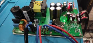
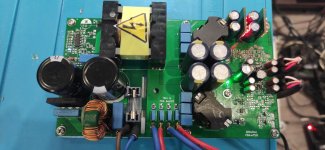
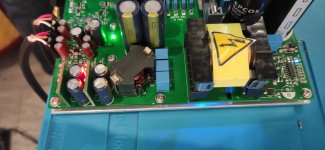
The radiator gets pretty hot. Small heatsink for two chips. It is necessary to install a fan or lower the supply voltage.
Would like less distortion as the output chokes
small and add distortion.
I ordered an OPA1656 chip from Ti to replace the NE5532.
Also need to replace the chokes with 22uH so that the tweeters (8ohm) work without a roll-off on the frequency response. Amplifier-constructor for the DIYer 🙂
I am 58 years old and my hearing is no longer as good as when I was young. I can confidently hear only 14,000 Hz. 🙂 Therefore, the throttle valve can be left at 10uH.
Attachments
Last edited:
for those folks trying to optimize the output filter, please remember that speakers are not a pure restive load. The way to fine tune the filter is to attach the speakers and measure the output with an AC voltmeter that is accurate to the frequency of interest or an oscilloscope. If you have an accurate impedance model of your speaker that will work as well. Things get more complicated if there is a crossover. What happens if your speaker is 6Ohms at 10KHZ and 12 Ohms at 20Khz or visa versa?
harmonic distortionThanks Polevka for your feedback
Attachments
No. The way to "fine tune" the output filter is not adapting it to your specific speaker but find a solution that yields a low impedance over the entire audio band. This can be achieved by PFFB.for those folks trying to optimize the output filter, please remember that speakers are not a pure restive load. The way to fine tune the filter is to attach the speakers and measure the output with an AC voltmeter that is accurate to the frequency of interest or an oscilloscope. If you have an accurate impedance model of your speaker that will work as well. Things get more complicated if there is a crossover. What happens if your speaker is 6Ohms at 10KHZ and 12 Ohms at 20Khz or visa versa?
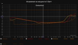
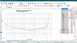
Confused? 🙂 It's static. In dynamics, everything is much worse. At LF and HF, due to small chokes, distortion is large. Distortion measurement at 1 kHz. does not say anything ... They can be small, but on LF and HF they will be large.Polevka,Okay! Harmonic analyzer software?
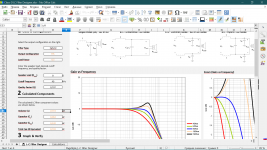
REW program. I have been using it for a long time. A wonderful thing.
Attachments

Last edited:
At low frequencies, distortion increases due to electrolytes. It is necessary to increase the capacity by 5 times and it will be good.
Excellent, matches the datasheet.
Excellent, matches the datasheet.
Hello,
after years of satisfaction with the gainclone,
I was curious about the class D,
so I bought the tpa3255 3e-audio stereo card;
After trying it, I am a little disappointed with
harsh treble and listening fatigue;
gainclone is much better on the mid and high band,
while the tpa 3255 fully wins on the bass,
energetic, deep and dry.
I added the zobel network, now i will implement the pffb,
I wonder why they don't always implement it since
these are few cheap but so important components.
I will not change the op amps,
the ne5532 is used in high end amplifiers and I don't think so
may affect the sound that much.
Most of these cards are copies of TI's EVM,
which I noticed not being the top of the design:
in SE mode, the two opamps are cascaded with gain one,
and this is perfectly useless; in addition also the two electrolytics
on the signal path could be avoided.
The two opamps supply the signal to the two branches,
but one takes the input from the other's output so
asymmetry is created: for example, the feedback capacitor
on the first opamp affects both branches;
this capacitor must also be increased by implementing the pffb.
If the gain of the two opamps is 1, why don't they have
tried to avoid its use, and use the inputs directly
of the chip, as is the case in so many chip-based amplifiers?
(e.g. tripath)
All comments, suggestions and opinions are welcome
Do you have any updates on your amp? I have the 3e board, but waiting for a few bits to arrive before I can assemble it
Fine. Thanks for the advice! I will definitely try to replace the electrolytic capacitors.At low frequencies, distortion increases due to electrolytes. It is necessary to increase the capacity by 5 times and it will be good.
Excellent, matches the datasheet.
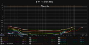
Take a closer look. The noise floor is less than 90 dB. at HF.
How will the MW LRS-200-36 power supply react to the increase in capacitor capacity?
Doubled the capacity of the capacitors. Nothing changed.
I assume that the problem is not in the capacitance of the capacitor.
Last edited:

I can't locate the post, at least one person didn't like the sound of PFFB. I always thought to solve issues first then to apply Feedback to improve the results not to hide problems.
Keep up the great work.
I am patiently waiting to receive mine.
Keep up the great work.
I am patiently waiting to receive mine.
I can't locate the post, at least one person didn't like the sound of PFFB. I always thought to solve issues first then to apply Feedback to improve the results not to hide problems.....
The problem is there is not enough open loop gain to make the feedback adequate. The inductor adds distortion and large amounts of feedback around the inductor would help to minimize it. Also, if the inductor is running too close to saturation it may be more non-linear. Running close to saturation creates more harmonic distortion.
This inductor looks like it might be pretty good choice for the TPA3255 designs... AGP2923 Series TH Shielded High Current Power Inductors: AGP2923 Series TH Shielded High Current Power Inductors | Coilcraft
Attachments


Use TPA3255 for its intended purpose and there will be no questions about the inductors used. When used in PBTL mode, it doesn't really matter what kind of inductors you have.This inductor looks like it might be pretty good choice for the TPA3255 designs... AGP2923 Series TH Shielded High Current Power Inductors:
For good stereo with low distortion (if there are passive filters in the speaker), you must use two TPA3255 microcircuits in PBTL mode. Even the cheapest filters from SAGAMI (7G14J-100M-R) provide very little signal distortion. Perhaps the best.
Distortion plots showing only 1 kHz frequency. are not the main ones.
This is a scam of "suckers". "Ponty for visitors" (Russian slang).
Естественно, я не пишу для колонок с импедансом 2 - 4 Ом. (автомобильная версия).
Пишу для обычных динамиков, качественное воспроизведение звука с высокой верностью - 8 - 16 Ом. (иногда больше). 🙂
Last edited:
It's not me, it's a forum glitch ...Polevka, I didn't write it ...
read personal correspondence
Last edited:
- Home
- Amplifiers
- Class D
- TPA3255 - all about DIY, Discussion, Design etc