3e audio amplifier units are on sale at multiple shops on AliExpress, but they are all officially shipped from 3e audio.
Each shop sets its own price.
Each shop sets its own price.
You can copy ElliJ's bypass-opamp mod. It will also bypass the DC-Blocking caps for the opamps.
For JLE board:
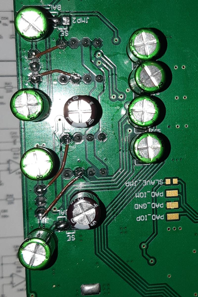
Electro caps encircled in red in below pic have a 2.5mm Lead Spacing, which means you can replace them with 2.5mm 22-23-2021 molex connectors, then connect each to 2.2uF MKT caps (use short twisted wirings, they are included in PFFB circuit!)
- Remove SE/BAL solder jumpers
- Remove opamps from sockets
- Connect J1-1 to socket A pin 1
- Connect J1-3 to socket A pin 7
- Connect J2-1 to socket B pin 1
- Connect J2-3 to socket B pin 7
My DAC juste received, test is OK with origianl configuration.
Testing the bypassing does not work. Amp goes in FAULT (red led). Not found yet why ...
D
Deleted member 148505
Hmm for our PFFB module it doesn't want the input resistor to be floating. Can you check with an external balanced line driver first? +in_GND_-in should be connected (do not test your expensive DAC lol)My DAC juste received, test is OK with origianl configuration.
Testing the bypassing does not work. Amp goes in FAULT (red led). Not found yet why ...
Unfortunately, i do not have another low cost DAC to test.
I tried with 1k between IN+ and IN-. Same FAULT. I mesured near 2.9V DC across the caps between the input and TPA (C1, C2, C3, C4). Strange ...
May be i should try the opposite, means that the board does not accept inputs referenced to the ground ? Should test without RA1, RA2, RB1 and RB2 (four SMD to desolder 🙁) ?
I see many articles recommending LLC switching power supplies for power supplies for class D amplifiers such as the TPA3255. I refer to those articles and select and use an LLC power supply.
However, reading the technical literature of LLC switching power supplies, it is stated that while it has high conversion efficiency and low noise, it is not suitable for loads with large fluctuations. This just means that LLC switching power supplies are not suitable for audio amplifiers.
I find this very mysterious. Someone please answer my question.
Such general statements are questionable. Load transient response of the unregulated LLC is similar to the classical linear toroidal power supply. With a fixed frequency tuned to LLC series resonant frequency output impedance is very low making this a quite stiff supply.
Load transient response of regulated LLC will vary with implementation of the control loop - making such generalization more or less useless.
I understand that some designers do not like LLC as the underlying theory is by far not simple. All in all due to the low losses and low component stress and high energy density this is my favourite smps topology nowadays.
Last edited:
D
Deleted member 148505
Unfortunately, i do not have another low cost DAC to test.
I tried with 1k between IN+ and IN-. Same FAULT. I mesured near 2.9V DC across the caps between the input and TPA (C1, C2, C3, C4). Strange ...
May be i should try the opposite, means that the board does not accept inputs referenced to the ground ? Should test without RA1, RA2, RB1 and RB2 (four SMD to desolder 🙁) ?
At startup, IN_X ramps up and charges the DC blocking caps to Vmid of AVDD (3.88VDC). That's why input capacitors are essential because of single supply internal opamps.
Also OUT_X ramps up to 1/2 PVDD. (That's why EVM needs DC blocking caps per ch in SE mode)
In our module with buffer opamps installed, input summing junction resistor sits at VMID of 12V supply. Ground reference is 1/2 of single 12V supply so input blocking caps are also required.
Have you tried putting 1K ohm from each input resistor to ground before or +IN to -IN directly?
Either startup sequence cannot be completed or the amp becomes unstable when we remove the buffer opamps.
Non-PFFB does not have that problem.
Regards,
Lester
Last edited by a moderator:
Lester, I took your suggestion and disabled PFFB on your board to see how it changed the output sound. I must say that I’m finding the "contained" sound of what I heard with PFFB implemented (regardless of how I changed caps here and there) completely gone with PFFB disabled. I’m hearing more spaciousness, more dynamics (yes, subjective) and just an overall more pleasing sound suited to my nature and listening tastes.
I’m not sure the SE to Diff buffer section was critically matched with PFFB but now that it’s out of the circuit, can I reasonably change RA3,RB3,RA5 & RB5 to 50K or 100K so I could use 2.2uF or 1uF (respectively) film caps on input, pre-op amps, so as to keep the high pass filter down to about 1.5 Hz or will the SE to Diff buffer be disrupted?
Thanks,
Pete
D
Deleted member 148505
Lester, I took your suggestion and disabled PFFB on your board to see how it changed the output sound. I must say that I’m finding the "contained" sound of what I heard with PFFB implemented (regardless of how I changed caps here and there) completely gone with PFFB disabled. I’m hearing more spaciousness, more dynamics (yes, subjective) and just an overall more pleasing sound suited to my nature and listening tastes.
I’m not sure the SE to Diff buffer section was critically matched with PFFB but now that it’s out of the circuit, can I reasonably change RA3,RB3,RA5 & RB5 to 50K or 100K so I could use 2.2uF or 1uF (respectively) film caps on input, pre-op amps, so as to keep the high pass filter down to about 1.5 Hz or will the SE to Diff buffer be disrupted?
Thanks,
Pete
Hi Pete,
You need to modify all the resistors + feedback caps since the opamps need to be in unity gain.
Best option for non-PFFB is to bypass the opamp section, use balanced input, and use 6.8uH Coilcraft VER2923-682KL + 0.68uF output capacitor for the filter.
In our living room I'm using non PFFB + 6.8uH/0.68uF + all muse caps (opamp is not bypassed).
Regards,
Lester
Thanks for the clarification Lester.
I just want to be clear about your statement "In our living room I'm using non PFFB + 6.8uH/0.68uF + all muse caps (opamp is not bypassed)."
Are you using SE or balanced input with this arrangement?
Pete
I just want to be clear about your statement "In our living room I'm using non PFFB + 6.8uH/0.68uF + all muse caps (opamp is not bypassed)."
Are you using SE or balanced input with this arrangement?
Pete
D
Deleted member 148505
Thanks for the clarification Lester.
I just want to be clear about your statement "In our living room I'm using non PFFB + 6.8uH/0.68uF + all muse caps (opamp is not bypassed)."
Are you using SE or balanced input with this arrangement?
Pete
I'm using only SE input that's why I can't bypass the opamps.
Regards,
Lester
D
Deleted member 148505
If you want to freely enable / disable the PFFB, VER2923-103KL + 1uF is better option.
Regards,
Lester
Regards,
Lester
Hello,This is the mod I made. I lifted the 1 leg on each op amp to remove their power. I wired the source sockets to the SMT caps, this was very tricky and tested my soldering skills (these caps can also be bypassed by soldering the wires to the other side of those caps). I will post the Panasonic caps I used later, I need to look it up. I did not try out the balanced DAC I used before I made the changes which means I can’t make any decent comparisons. However the DAC was a Scarlett Solo which is good but not expensive. The overall improvement was really impressive. It sounds less bright with much better midrange and bass without sounding boomy.
Did you disable the PFFB part on your board ?
Thanks !
I don’t think I did disable the PFFB. The only thing I disconnected was the power to the op amps. I think the PFFB will still be working, it would still be part of the circuit. I know that if I had removed the caps where my bypass wires connect to it would disable the PFFB but I did not remove them. I am not that knowledgeable about electronics.
I just ordered 3E Audio TPA3255 board. And planning to buy a JLE board as well. Which power supply you guys suggest for these two amplifier boards?
Meanwell LRS 36V or 48V or any other option you guys suggest?
Thanks,
Simar
Meanwell LRS 36V or 48V or any other option you guys suggest?
Thanks,
Simar
A noob question here. Is there any difference in audio quality between 36V and 48V?
I am more concerned about audio quality rather than output power. So does voltage rating makes difference here?
Thanks
I am more concerned about audio quality rather than output power. So does voltage rating makes difference here?
Thanks
- Home
- Amplifiers
- Class D
- TPA3255 - all about DIY, Discussion, Design etc