Does anyone try FX502s at 12V-19V power supply ?
On datasheet 3250 can work on 12V min, but does this apply for FX502s product ?
hi andre
asome guys use more then 24V-eg. 28V to let the internal regulator work. the reason is that the configuration (LM317 resistors) are set for 24V output. the lm317 needs about 3v more to work correct. some guys wrote that they are using 24V or less voltage and are happe. technical that means that the reagulator is not working. actually i do not know what happend with ripple if the regulator is not working.
technically you can drive the amp with 12V . but its really not much power. so give it a try.....and report back please.
btw
any body try the amp with 4R speakers??????????...if i remember i did some test with 4 R test but after approx. 25min the heatsink gots very hot...then i stopped
output filter set to 8R configuration
Hi
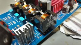
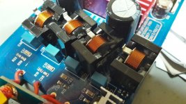
the output filter are original with air coils..i use the Würht 10µ (11,1µH measured) and the tdkfor 8R configuration
original was 0,82µ and in the second am 1µ
opamps are 4562 smps is changed to the LRS-150-24V.
in my configuration (LM317 is set to 24--> 20V)
the other smps is much better at SQ compared tot he original!
but i think that s no secret.😀
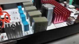
coils
74439370100
caps
0,680µF B32529C1684J000
.47µF
B32529C1474K000
chris
Hi
the output filter are original with air coils..i use the Würht 10µ (11,1µH measured) and the tdkfor 8R configuration
original was 0,82µ and in the second am 1µ
opamps are 4562 smps is changed to the LRS-150-24V.
in my configuration (LM317 is set to 24--> 20V)
the other smps is much better at SQ compared tot he original!
but i think that s no secret.😀
coils
74439370100
caps
0,680µF B32529C1684J000
.47µF
B32529C1474K000
chris
Attachments
...
btw
any body try the amp with 4R speakers??????????...if i remember i did some test with 4 R test but after approx. 25min the heatsink gots very hot...then i stopped
No problem with 4R speakers. Using it in my study with a pair of 87 dB/Watt and 4R speakers. It's still extremely cool.
By the way, another mod you can try: Place some copper foil around the plastic body of the OP-amps and be sure to connect the foil to ground (ground is nearby at the volume control). Don't know about the sonic difference but it reduces the background noise level from the output of the OP-amps.
If so, that is a strong indicator for a poor pcb design imho.No problem with 4R speakers. Using it in my study with a pair of 87 dB/Watt and 4R speakers. It's still extremely cool.
By the way, another mod you can try: Place some copper foil around the plastic body of the OP-amps and be sure to connect the foil to ground (ground is nearby at the volume control). Don't know about the sonic difference but it reduces the background noise level from the output of the OP-amps.
These Würth inductors aren't that good for class-d as they are soft-saturation carbonyl iron powder compound cores. Last time I compared these type of inductors to ferrite ones we'd seen a lot of k2 distortion. This results in some sound coloration like triode tube amps do. They are pretty much like the Coilcraft XAL1510 series.
These Würth inductors aren't that good for class-d as they are soft-saturation carbonyl iron powder compound cores.
...
Yes, Inductance starts to change at about 3A.
https://katalog.we-online.de/pbs/datasheet/74439370100.pdf
Better choice:
(for the size)
https://katalog.we-online.de/pbs/datasheet/7447709100.pdf
Hi to all
Strongbow60...sorry ...but implement a foil is to tricky for me.
@coils
thanks to doctor and voltwide for the hint.
Strongbow60...sorry ...but implement a foil is to tricky for me.
@coils
thanks to doctor and voltwide for the hint.
Last edited:
Thank you DUG for your hint....
so that mean at 3 Amps the saturation's starts:
its about P=I^2 *R = 3^2 *8 = 9+8= 72 Watt ...into 8 ohms
i think i can leave with...but the k2 is maybe not so nice....🙄
i have to think about another coil
doctor once tested these....7443631000...much bigger...but...
thanks
chris
so that mean at 3 Amps the saturation's starts:
its about P=I^2 *R = 3^2 *8 = 9+8= 72 Watt ...into 8 ohms
i think i can leave with...but the k2 is maybe not so nice....🙄
i have to think about another coil
doctor once tested these....7443631000...much bigger...but...
thanks
chris
Thank you DUG for your hint....
so that mean at 3 Amps the saturation's starts:
its about P=I^2 *R = 3^2 *8 = 9+8= 72 Watt ...into 8 ohms
...
Look at peak current.
...
doctor once tested these....7443631000...much bigger...but...
...
7443631000 here
https://katalog.we-online.de/pbs/datasheet/7443631000.pdf
AAhh....
if i compare these 2 diagrams then i can recognize what you want to say me 😀
thx
chris
..burst test with original smps....
i want to test the origianl smps which comes with the amp
..same test procedure as here...
https://www.diyaudio.com/forums/class-d/309813-wrong-tpa3255-65.html#post5636968
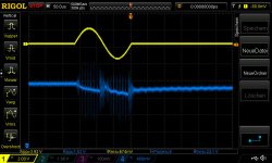
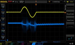
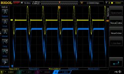
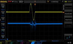
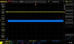
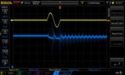
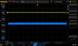
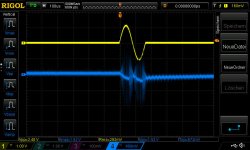
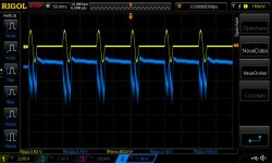
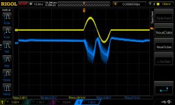
i try a loop test with a burst of 40Hz, period is 100ms, 1 Cycle. i try 800mVrms in or 1300mVrms into the amps input. at 4R load its more visible.
original amp and caps....TPA3255..measurement directly on the amps supply terminal
pic 1 40hz 800mVrs burst pic 2 more burst view (50ms/DIV)
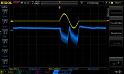
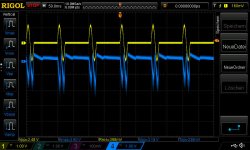
pic 3 40hz 1300mVrms pic 4 more burst view (50ms/DIV)
pic 5 6khz 800mVrms pic 6 more burst view (50ms/DIV)
pic 7 6khz 1300mVrms pic 8 more burst view (50ms/DIV)
i want to test the origianl smps which comes with the amp
..same test procedure as here...
https://www.diyaudio.com/forums/class-d/309813-wrong-tpa3255-65.html#post5636968
i try a loop test with a burst of 40Hz, period is 100ms, 1 Cycle. i try 800mVrms in or 1300mVrms into the amps input. at 4R load its more visible.
original amp and caps....TPA3255..measurement directly on the amps supply terminal
pic 1 40hz 800mVrs burst pic 2 more burst view (50ms/DIV)
pic 3 40hz 1300mVrms pic 4 more burst view (50ms/DIV)
pic 5 6khz 800mVrms pic 6 more burst view (50ms/DIV)
pic 7 6khz 1300mVrms pic 8 more burst view (50ms/DIV)
Attachments
-
 fxpsu1_6khz_4Routput_1Cycle_20msperiode_1300mVrms input burst_2.jpg81.7 KB · Views: 94
 -
 fxpsu1_6khz_4Routput_1Cycle_20msperiode_1300mVrms input burst_1.jpg76.4 KB · Views: 85
 -
 fxpsu1_6khz_4Routput_1Cycle_20msperiode_800mVrms input burst_2.jpg81.1 KB · Views: 88
 -
 fxpsu1_6khz_4Routput_1Cycle_20msperiode_800mVrms input burst_1.jpg77.7 KB · Views: 674
 -
 fxpsu1_40hz_4Routput_1Cycle_100msperiode_1300mVrms input burst_2.jpg83.4 KB · Views: 681
 -
 fxpsu1_40hz_4Routput_1Cycle_100msperiode_1300mVrms input burst_1.jpg72.4 KB · Views: 687
 -
 fxpsu1_40hz_4Routput_1Cycle_100msperiode_800mVrms input burst_2.jpg80.3 KB · Views: 703
 -
 fxpsu1_40hz_4Routput_1Cycle_100msperiode_800mVrms input burst_1.jpg71.4 KB · Views: 720
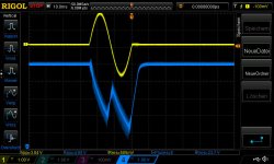
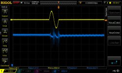
pic 9 12khz 800mVrms pic 10 more burst view (50ms/DIV)
pic 11 12khz 1300mVrms pic 12 more burst view (50ms/DIV)
pic 13 16khz 800mVrms pic 14 more burst view (50ms/DIV)
pic 15 16khz 1300mVrms pic 15 more burst view (50ms/DIV)
pic 11 12khz 1300mVrms pic 12 more burst view (50ms/DIV)
pic 13 16khz 800mVrms pic 14 more burst view (50ms/DIV)
pic 15 16khz 1300mVrms pic 15 more burst view (50ms/DIV)
Attachments
-
 fxpsu1_16khz_4Routput_1Cycle_20msperiode_1300mVrms input burst_2.jpg76.4 KB · Views: 69
 -
 fxpsu1_16khz_4Routput_1Cycle_20msperiode_1300mVrms input burst_1.JPG73.4 KB · Views: 72
 -
 fxpsu1_16khz_4Routput_1Cycle_20msperiode_800mVrms input burst_2.jpg77.1 KB · Views: 80
 -
 fxpsu1_16khz_4Routput_1Cycle_20msperiode_800mVrms input burst_1.jpg74.4 KB · Views: 77
 -
 fxpsu1_12khz_4Routput_1Cycle_20msperiode_1300mVrms input burst_2.jpg79.6 KB · Views: 78
 -
 fxpsu1_12khz_4Routput_1Cycle_20msperiode_1300mVrms input burst_1.jpg76.7 KB · Views: 78
 -
 fxpsu1_12khz_4Routput_1Cycle_20msperiode_800mVrms input burst_2.jpg78 KB · Views: 81
 -
 fxpsu1_12khz_4Routput_1Cycle_20msperiode_800mVrms input burst_1.jpg75.6 KB · Views: 93
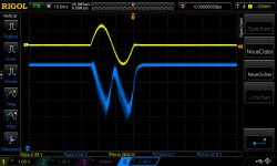
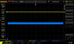
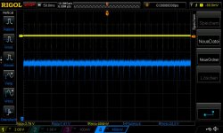
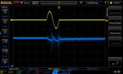
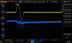
to compare to the LRS 150 -24...set to 24,01V mean well smps
pic 17 40hz 800mVrms pic 18 more burst view (50ms/DIV)
pic 19 40hz 1300mVrms pic 20 more burst view (50ms/DIV)
pic 21 6khz 800mVrms
pic 22 6khz 1300mVrms
in my opinion.....power by the original is not that bad...but is more noisy....
chris
pic 17 40hz 800mVrms pic 18 more burst view (50ms/DIV)
pic 19 40hz 1300mVrms pic 20 more burst view (50ms/DIV)
pic 21 6khz 800mVrms
pic 22 6khz 1300mVrms
in my opinion.....power by the original is not that bad...but is more noisy....
chris
Attachments
-
 LRS150-24_6khz_4Routput_1Cycle_20msperiode_1300mVrms input burst_originamp_1.jpg74.1 KB · Views: 89
 -
 LRS150-24_6khz_4Routput_1Cycle_20msperiode_800mVrms input burst_originamp_1.jpg73.2 KB · Views: 86
 -
 LRS150-24_40hz_4Routput_1Cycle_100msperiode_1300mVrms input burst_originamp_2.jpg79.8 KB · Views: 84
 -
 LRS150-24_40hz_4Routput_1Cycle_100msperiode_1300mVrms input burst_originamp_1.jpg73.1 KB · Views: 81
 -
 LRS150-24_40hz_4Routput_1Cycle_100msperiode_800mVrms input burst_originamp_2.jpg80.1 KB · Views: 93
 -
 LRS150-24_40hz_4Routput_1Cycle_100msperiode_800mVrms input burst_originamp_1.jpg72.8 KB · Views: 93
Last edited:
at hard burst of 40HZ ( 1300mVrms input burst) both amps drop the voltage.
re checked with DMM
original psu fx502spro 24,23V ---> 23,85V
LRS150-24 (24,01) 24,01V ---> 23,81V
re checked with DMM
original psu fx502spro 24,23V ---> 23,85V
LRS150-24 (24,01) 24,01V ---> 23,81V
frequency response after changing output filter
Hi
here are some measurements...i did have the THD equipment...
+
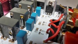
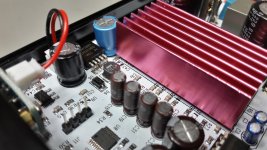
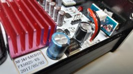
2 pics with changed caps inside = input caps are now the 10µF elna silmic 2
and at the white board amp (amp2) i changed additionally the caps at the regulator. regulator is the LM2596S. SQ compare not done....in the new year😀
chris
Hi
here are some measurements...i did have the THD equipment...
+
2 pics with changed caps inside = input caps are now the 10µF elna silmic 2
and at the white board amp (amp2) i changed additionally the caps at the regulator. regulator is the LM2596S. SQ compare not done....in the new year😀
chris
Attachments
-
fx502spro_1_frequency response blue boardv3_other output filter.pdf452.4 KB · Views: 216
-
fx502spro_2_frequency response white boardv5_other output filter.pdf452.4 KB · Views: 159
-
 FX502spro_v5_white pcb_caps at regulator and input caps_1.jpg685.1 KB · Views: 320
 -
 FX502spro_v5_white pcb_caps at regulator and input caps_2.jpg590.9 KB · Views: 324
Chris, since you start modding the input caps ~
How is 2 onboard regulator (1 Buck, 1 LDO)
- much noise output by the LDO?
for the sake of your opamp LM4562 ~😀, any thoughts, shldnt replace LDO with low noise?
How is 2 onboard regulator (1 Buck, 1 LDO)
- much noise output by the LDO?
for the sake of your opamp LM4562 ~😀, any thoughts, shldnt replace LDO with low noise?
Chris, since you start modding the input caps ~
How is 2 onboard regulator (1 Buck, 1 LDO)
- much noise output by the LDO?
for the sake of your opamp LM4562 ~😀, any thoughts, shldnt replace LDO with low noise?
Hi
next year ...😀
as you know from my journey of my tpa3255 boards i learn about this regulators. i ordered different types....testing learning...will see
in the fx502sprois the "better" version of the lm2575 (52khz buck) implemented--the LM2596(150khz buck)
wish all of you a happy new year 2019!!!
luckly I planed to use this for my tpa3255 YJ boards...😛
its really tight !😀
SQ compare between both amps not done. same opamp (4562) same input caps (elna silmic 2) but now different coils
chris
Attachments
Have someone already measured real power output of this Fx-audio with 24V adapter that comes with the amp? or some measurements with 32V adapter or so... ?
Already ordered one amp, so once i get it i plan to elaborate alot about this but just curious in advance 🙂
Already ordered one amp, so once i get it i plan to elaborate alot about this but just curious in advance 🙂
atHave someone already measured real power output of this Fx-audio with 24V adapter that comes with the amp? or some measurements with 32V adapter or so... ?
Already ordered one amp, so once i get it i plan to elaborate alot about this but just curious in advance 🙂
Hi Wiliks
at post 471 i did some measurements. https://www.diyaudio.com/forums/class-d/315681-tpa3250-listening-48.html#post5419119
the implementation of the TPA3250 in this housing is not the best for pushing lot of watts.
closed housing!
what i not like is the adapter for the power socket 230V at this psu😡....be careful at the power socket in the wall for connecting and disconnecting
the original psu is not bad...better is for me the lrs 150-24V psu (21euro)
if you want to push more power it happend often that the amps go into the error mode, but its not a error of the chip - its realize the undervoltage of the original psu...nevertheless its a lot of power what you can go with the origin psu.
4 ohm speakers do not really work with loud level....my experience
i personally can leave with my mods and the power of this nice amp!!!😉
amp with 10-20W and less distortion is my target...
chris
Last edited:
- Home
- Amplifiers
- Class D
- TPA3250 somebody is listening?