Did you try tracing the mute pin (12) trace to see where it goes? With two chips you should have two traces maybe running both into a resistor, and I suppose the other side of the resistor is grounded/pulled high by the BT chip?
Having some DC on the mute pins will most likely keep the outputs hi-z. You need to check where that mute signal is coming from.
edit: would help if you could remove the heatsinks and take photo from the top so the traces are clear.
Having some DC on the mute pins will most likely keep the outputs hi-z. You need to check where that mute signal is coming from.
edit: would help if you could remove the heatsinks and take photo from the top so the traces are clear.
Last edited:
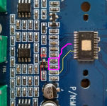
I managed to trace parts of it. Here is an overview (top right is where the bluetooth chip was located):

I can measure continuity between pin12 on both the chips, so I guess they are connected in parallel. This is zoomed in on the upper tpa chip:

As you can see I managed to trace parts of it, but I didn't manage to trace the bottom right pin of the transistor.
Wouldn't the amp unmute if I grounded pin 12?
I can measure continuity between pin12 on both the chips, so I guess they are connected in parallel. This is zoomed in on the upper tpa chip:
As you can see I managed to trace parts of it, but I didn't manage to trace the bottom right pin of the transistor.
Wouldn't the amp unmute if I grounded pin 12?
You can try to remove the transistor and short the top pad of it to the gnd of the cap that's next to it (upper). That should pull the Mute pins low.
Most probably the gate of the transistor goes to some resistor and then to the BT chip. No need to trace it further.
Most probably the gate of the transistor goes to some resistor and then to the BT chip. No need to trace it further.
Strange. Do both chips get power? Can you measure AC input signal on the audio input pins?
edit: I think the signal has to go through the front end with all the tone controls. But if it worked before you removed the BT chip, it should work now. There could be extra stuff from the front end tied to the BT chip but I doubt it.
edit: I think the signal has to go through the front end with all the tone controls. But if it worked before you removed the BT chip, it should work now. There could be extra stuff from the front end tied to the BT chip but I doubt it.
Last edited:
Yes, I have power to both chips and measured AC on the audio inputs. However I don't read any voltage on pin 2 (SDZ):
"Shutdown logic input for audio amp (LOW = outputs Hi-Z, HIGH = outputs enabled). TTL logic levels with compliance to AVCC."
I guess it should be possible to jumper a wire to this pin to supply it with voltage?
"Shutdown logic input for audio amp (LOW = outputs Hi-Z, HIGH = outputs enabled). TTL logic levels with compliance to AVCC."
I guess it should be possible to jumper a wire to this pin to supply it with voltage?
I see in your pictures that pin goes to a resistor then some diode I guess. But the pin should be ok for whatever Pvcc is. Maybe power the pins through the first resistor, not directly on the pin.
Finally got time to try that and now it works again. Unfortunately there is still way to much hiss. Anyone has another 2.1 board they recommend?
there are many people here who have complained about too much hiss. The solution was nearly always to reduce the gain of the TPA3116.
Yes, first try reducing the gain from TPA3116 chip, if that doesn't solve it then you might want to bypass the whole frontend. I suppose there's tone controls on the board?
edit: since you have two chips, and I remember SYNC pin having a trace out of it, the chips might be in a master/slave config. Gain settings are different between master/slave. the mod itself is pretty simple, there's two resistors for each chip, and master on least gain needs only one actually.
2nd edit: yeah looking at your photos you seem to have 39k/100k combo for both. that means 32dB gain for both master/slave, just that for each the resistor positions are swapped. no wonder you have hiss, the gain it's pretty high. I'd go for lowest gain 20dB. R1=5.6K and no R2 for master and 51K for both R1/R2 for slave, in case the second chip is slaved. I can't tell from the photos, and as it happens the 100k/39k is the single combo that's shared as values, between both master/slave (but swapped positions). So you'll have to measure to find out if the second chip is master or slave config, and replace the resistor values accordingly. also I think the hiss stuff is valid for any board with this chip. since you already have the board and modded it, you're better of in the end modifying it for gain as well.
3rd edit: also changing the gain from 32dB to 20dB increases the input impedance from 15K to 60k, which in turn lowers the need for higher value for input coupling cap. say you have a 2uF cap, you'd need a 0.47uF for the same frequency response. in case you want to upgrade the coupling caps later. of-course you can just leave the existing caps. but increasing the input impedance from 15k to 60k and keeping the existing coupling caps would allow for more LF to pass. if that's an issue, lower the coupling caps accordingly
Last edited:
These resistors are connected to pin 8 or? I tried to find them but didn't manage. But it seems you have spotted them from the pictures?
Yes you are correct. The upper chip has the 100k to ground, and the 39k to an capacitor and then to ground. The lower chip is the opposite as you mentioned. So the upper chip is in slave config and lower in master? I'll try to replace the resistors
Ye, upper chip is slave, so replace 100K with 51K (or 50K, not critical), and 39K replace with also 50-51K. Maybe parallel two 100K on each resistor place if you don't have 50-51K.
The lower is master, so completely remove the 100K and leave it open and replace 39K with 5.6K.
That should fix the hiss issues.
The lower is master, so completely remove the 100K and leave it open and replace 39K with 5.6K.
That should fix the hiss issues.
Ye, upper chip is slave, so replace 100K with 51K (or 50K, not critical), and 39K replace with also 50-51K. Maybe parallel two 100K on each resistor place if you don't have 50-51K.
The lower is master, so completely remove the 100K and leave it open and replace 39K with 5.6K.
That should fix the hiss issues.
Its kind of hard to search for this exact board model on this thread, but you seem to know a lot about it!
I have the same board design, but since I'm new to this I'm kind of lost.
You might be able to help me out, I have two major problems.
1- When playing the amp through bluetooth, I have a crazy hissing sound that stops for a second every 15 seconds, I suspect its because of a ground loop? If I connect the bluetooth module to an isolated 5v would that fix the problem? If so, which pins do I need to disconnect and connect to the other 5v? Video
2- There is also a noticeable hiss while playing through the 3.5mm jack, maybe its the "common" gain problem? If so which resistors do I need to change exactly?
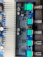
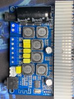
Pictures of the board:
I'm a visual person specially that I'm a newbie.
Thank you!
Attachments
Its kind of hard to search for this exact board model on this thread, but you seem to know a lot about it!
i used the same model for my nephew's boom-box (AIYIMA TPA3116 Subwoofer Amp Board 2,1 Channel High Power Bluetooth 5,0 Audio Amp DC12V-24V 2*50W + 100W).
my amp did not hiss neither with bluetooth nor 3,5 mm jack, using laptop-brick as supply. so your amp may have an issue that cannot be fixed just by adjusting gain.
by the way: there is a connection for USB on this board. if you add a connector it plays mp3's from a USB-stick!
Attachments

i used the same model for my nephew's boom-box (AIYIMA TPA3116 Subwoofer Amp Board 2,1 Channel High Power Bluetooth 5,0 Audio Amp DC12V-24V 2*50W + 100W).
my amp did not hiss neither with bluetooth nor 3,5 mm jack, using laptop-brick as supply. so your amp may have an issue that cannot be fixed just by adjusting gain.
by the way: there is a connection for USB on this board. if you add a connector it plays mp3's from a USB-stick!
I bought 3 of them and they all have the same problem, doubt its a faulty unit kinda thing!
Also the bluetooth hiss is completely different than the 3.5mm noise.
Its not AIYIMA but its almost identical.
I bought 3 of them and they all have the same problem, doubt its a faulty unit kinda thing!
OK .... the image looked sooo similar to my amp 😱
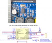
check the image below: the photo shows the bluetooth chip with pin numbers. if you can read the name on it, try to find a data sheet.
i added one schematic that i found for my aiyima-board, maybe it can help to identify the power connections - however, please check it, maybe it's not the right chip!
Attachments
OK .... the image looked sooo similar to my amp 😱
check the image below: the photo shows the bluetooth chip with pin numbers. if you can read the name on it, try to find a data sheet.
i added one schematic that i found for my aiyima-board, maybe it can help to identify the power connections - however, please check it, maybe it's not the right chip!
I believe what is written is ac21bp09608-5a8, but I couldn't find anything on google!
Edit: Just checked, 12 is indeed the 3.3v and ground, do you have any idea if it can run on 5v? and whats the purpose of the 105 cap?
Last edited:
Edit: Just checked, 12 is indeed the 3.3v and ground, do you have any idea if it can run on 5v? and whats the purpose of the 105 cap?
I can send the complete schematic i have, once i get back to my computer. The 105 cap is probably a decoupling cap.
- Home
- Amplifiers
- Class D
- TPA3116D2 Amp