Yeah, I noticed the same thing AFTER I made the purchase, of course. 🙁
I will contact the seller to get clarification.
Fingers crossed.
I will contact the seller to get clarification.
Fingers crossed.
About the Audiobah board compared to the black and blue board. Is it possible to move the caps closer to the chip. If so, which make a difference? Should all caps be exchanged to these tiny ones in the Audiobah?
Last edited:
Yeah, I noticed the same thing AFTER I made the purchase, of course. 🙁
I will contact the seller to get clarification.
Fingers crossed.
It just might be that the photos got mixed up as the other one doesn't show an internal photo. We do know that the 3118 does not have a visible heatsink as the powerpad is faced down and soldered to the vias on the PCB as the heatsink. At least Amazon is easy to get things changed and they are good with customer service.
I got too nervous and canceled the order. 😀 I did send a question to the seller, and hopefully will hear back from them.
Here is another option: Amazon.com: Signstek SA-36A Pro Upgrade Version 20W*2 TA2020 Class HIFI Digital T AMP Stereo Amplifier with a Adapter Black: Electronics
No inside picture, but 12-24vdc on the back lends more confidence.
Here is another option: Amazon.com: Signstek SA-36A Pro Upgrade Version 20W*2 TA2020 Class HIFI Digital T AMP Stereo Amplifier with a Adapter Black: Electronics
No inside picture, but 12-24vdc on the back lends more confidence.
I got too nervous and canceled the order. 😀 I did send a question to the seller, and hopefully will hear back from them.
Here is another option: Amazon.com: Signstek SA-36A Pro Upgrade Version 20W*2 TA2020 Class HIFI Digital T AMP Stereo Amplifier with a Adapter Black: Electronics
No inside picture, but 12-24vdc on the back lends more confidence.
Why don't you just get the gold faced TPA3118D2 version? It comes with 24 volt ps and is only $5 more? TPA3118D2 sound quality and technology is superior to old-Tripath TA2020 technology.
Amazon.com: SMSL SA-36A Pro 20WPC TPA3118D2 Digital Amplifier AMP + 24V Power Supply Golden: Electronics
I got too nervous and canceled the order. 😀 I did send a question to the seller, and hopefully will hear back from them.
Here is another option: Amazon.com: Signstek SA-36A Pro Upgrade Version 20W*2 TA2020 Class HIFI Digital T AMP Stereo Amplifier with a Adapter Black: Electronics
No inside picture, but 12-24vdc on the back lends more confidence.
I don't know what they are trying to pull. The description states TA2020. The max with that chip is around 14Volts. It states below Power Supply: DC9-14V . That makes it correct for the TA2020. I think someone is mixing up pictures from the SA-36A (which is a TA2020) and the SA-36A Pro which is a TPA chip.
Why don't you just get the gold faced TPA3118D2 version? It comes with 24 volt ps and is only $5 more? TPA3118D2 sound quality and technology is superior to old-Tripath TA2020 technology.
Amazon.com: SMSL SA-36A Pro 20WPC TPA3118D2 Digital Amplifier AMP + 24V Power Supply Golden: Electronics
I agree. That is described correctly and the sound of the TPA is much better than the old Tripath chips.
Does the 3118 have similar issues with 24vdc as the 3116? Isn't 19-20vdc the preferred voltage?
Also, instant gratification with Prime shipping is a bonus. 😀
Also, instant gratification with Prime shipping is a bonus. 😀
Ok, ordered one of these:Latest Hifi 2 0 Stereo Output Digital Power Amplifier TPA3116 50WX2 BY WLX | eBay

will see how it sounds next to a stock YJ Blue/Black board. Any improvement opportunities you guys spot on there? output filters seem vanila, candidates for mod?
will see how it sounds next to a stock YJ Blue/Black board. Any improvement opportunities you guys spot on there? output filters seem vanila, candidates for mod?
Last edited:
Does the 3118 have similar issues with 24vdc as the 3116? Isn't 19-20vdc the preferred voltage?
Also, instant gratification with Prime shipping is a bonus. 😀
I think it was Saturnus who said that the optimal voltage for best sound quality was actually ~21 volts. However, I don't think that the difference is large. I have not personally heard a TPA31xx running on 24 volts myself and would not worry about it. You can always plug in a $6 19v laptop supply if you wanted to A/B it.
I think it was Saturnus who said that the optimal voltage for best sound quality was actually ~21 volts. However, I don't think that the difference is large. I have not personally heard a TPA31xx running on 24 volts myself and would not worry about it. You can always plug in a $6 19v laptop supply if you wanted to A/B it.
I have a CPS-3205 adjustable power supply and hear very little difference between 21V and 24V. Maybe a little more clear at 21V while sacrificing some power vs 24V. Not a huge difference for sure
Any improvement opportunities you guys spot on there? output filters seem vanila, candidates for mod?
Why does it have all those little electrolytic caps between the poly input caps and the heat sink? Electrolytics should only be on the DC power rails.
1. There should be 2 DC de-coupling electrolytic caps mounted as closely as possible to the two Vcc pins on each end of the chip. This has a bank of caps all on one side. Add a Panasonic 330uF 25v OSCON SEPF ultralow ESR caps to each end of the IC, as close as possible.
2. Add 330pF and 10 ohm bootstrap snubbers if not already there on the output side.
-- later --
3. Swap inductors to higher quality Bourns, Coilcraft, or Wurth - but wait on this and see if they heat up too much or sound good/bad.
4. Change input caps to 3.3uF to extend bass response.
Thanks xrk!


Hi xrK97,
After I implemented the bootstrap snubbers, I put back the Sillimer II 1000uF 50V, it actually sounds better than my previous 330uf CD. I am keeping the Sillimic II. I will wait for the inductor for the next mod or change the 2.2uF Wima MKP10 to a 3.3uF xxx (have't decided yet).
I just ordered the board JK44 is looking at now, just wait and see.
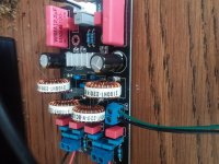
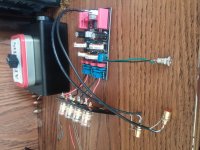
Hey guys, i hooked up my modded yj black/blue board today and there was no sound going out of my speakers. No speaker pop, no hiss, no nothing. Board also doesnt get warm at all, like its not getting power at all. Im using a 19v 3.42a laptop brick for now. Unfortunately i was impatient and didnt test the board before i modded it so i dont know if it was broken from the get go. Any reasons why this is happening?
Attachments
I'm having a look at this image
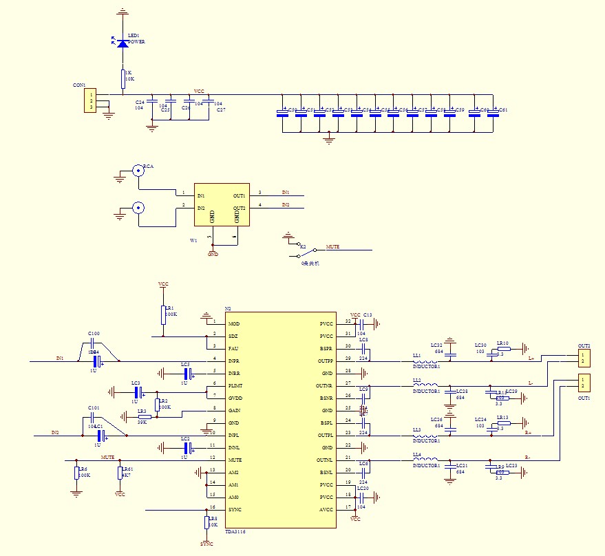
the schematic drawing
Looks like the output snubber is 4 10nF capacitors and 4 surface mount resistors (3.3 ohm i think)? I am a beginner at this! Surface mount scares me LOL
An externally hosted image should be here but it was not working when we last tested it.
and 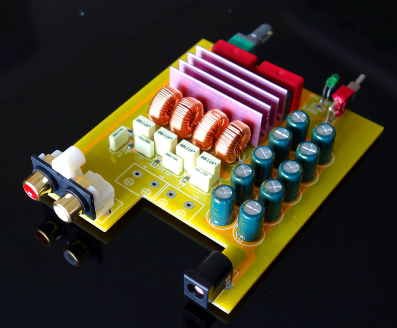
the schematic drawing
An externally hosted image should be here but it was not working when we last tested it.
Looks like the output snubber is 4 10nF capacitors and 4 surface mount resistors (3.3 ohm i think)? I am a beginner at this! Surface mount scares me LOL
Hey guys, i hooked up my modded yj black/blue board today and there was no sound going out of my speakers. No speaker pop, no hiss, no nothing. Board also doesnt get warm at all, like its not getting power at all. Im using a 19v 3.42a laptop brick for now. Unfortunately i was impatient and didnt test the board before i modded it so i dont know if it was broken from the get go. Any reasons why this is happening?
Those are some nice mods you have there. Boards generally don't come DOA, but you should have tested it first! Tisk, tisk...
In any case, the TPA3116D2 is pretty well protected and idiot proofed - except to ESD zaps. You can short the outputs, or run it until it thermally trips. When it is silent and cold, it may be in shutdown or mute mode. Check the SDZ and Mute pins and see where they go and if the components controlling those logic levels are good. The other thing that will make a chip silent is a bad bootstrap cap. I see you upgraded to a nice ceramic (or tantalum) variety. Just one bad bootstrap and the whole chip shuts down. Put the stock ones back on or check to see if you have a fried one. That's all I can think of for now.
Those WIMA's are not bipolars, right? Could be that you reversed sides, I think the marks should face out? Or the same as marks shows on pcb.Hey guys, i hooked up my modded yj black/blue board today and there was no sound going out of my speakers. No speaker pop, no hiss, no nothing. Board also doesnt get warm at all, like its not getting power at all. Im using a 19v 3.42a laptop brick for now. Unfortunately i was impatient and didnt test the board before i modded it so i dont know if it was broken from the get go. Any reasons why this is happening?
Have you checked the power line of the PSU, and your input socket what's positive/negative?
Just curios; why polyesters and 100V only on DC decoup? Cool inductors though!
Last edited:
I'm having a look at this image
An externally hosted image should be here but it was not working when we last tested it.and
the schematic drawingAn externally hosted image should be here but it was not working when we last tested it.
Looks like the output snubber is 4 10nF capacitors and 4 surface mount resistors (3.3 ohm i think)? I am a beginner at this! Surface mount scares me LOL
The 10nF and 3.3R is the post LC filter snubber. There is a pre-LC filter snubber that connects to the point between the chip output pin and the inductor. That snubber is in the EVM circuit and uses 330pF and 10R in series and R to ground. Where did you get the schematic?
Hey guys, i hooked up my modded yj black/blue board today and there was no sound going out of my speakers. No speaker pop, no hiss, no nothing. Board also doesnt get warm at all, like its not getting power at all. Im using a 19v 3.42a laptop brick for now. Unfortunately i was impatient and didnt test the board before i modded it so i dont know if it was broken from the get go. Any reasons why this is happening?
Put a meter across the DC power input terminals and make sure you see the 19V you expect. Sorry if you already did that! I know it's like the most rudimentary trouble-shooting you can do. I only mention it because I've somehow screwed up the wiring of the DC input receptacle... multiple times. It's like the easiest part of the all the tpa311x hacking I've done, and yet I keep doing something wrong.
It's pretty easy to look at the board and see the main power trace leading up to the chip itself. You should be able to check that you have power across GND all the points leading up to the chip. You may have already checked these things, but if not, they are quick and easy.
Perhaps that's one upside to a power on/off "thump" - useful for basic debugging. 🙂 Also, both of my YJBlue boards---in the absence of a volume pot---create a quiet "hiss" on the speakers if the inputs are not connected. I have to put my ear right up to the speaker to hear it, but it's there. Could also be a useful "feature" in your case.
- Home
- Amplifiers
- Class D
- TPA3116D2 Amp