So, we're back to the discussion where you suggested putting 10000uF off board and the easiest way to achieve this is to wire up 10 x 1000uF capacitors-- of something like Panasonic FC type-- in parallel before the VCC+ terminal.
and that is all correct? no need for any diodes, or any other components?
Just a cap bank in parallel.
And prior discussion says while 200uF is spec on board, it may not be quite enough and may be expanded but do NOT use more than 1000uF on board near the chip-- and to use the smallest form factor capacitor possible for this position.
Thanks for explaining this again.
So far, my preferred YJ blue mods are Wima replacement caps on the inputs, Nichicon 35v 1000uF as power caps, and the above mentioned Bourns inductors.
Seems to have good thump and transparency.
The advantage to smaller caps on board may be more frequent discharge/charge for better coupling next to the chip, as to deal with whatever has been inducted from PSU to it. That's why they may be recommended by TI. Capacitors just aren't amazing at attenuating noise in DC since there isn't a regular cycle.
Anyways, ya, give something like that a try. You can use bigger off board caps but quality reflects how many times you want to multiply.
Maybe I should try putting this off board on my YJ Blue boards power supply 😉.
It'll have too large ESR and ESL by the time you've wired it in. What's likely to sound better is something like this... Sit the amp on top 😀
Attachments
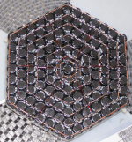
That monster cap bank is very cool. What is the total Farad rating? You really have to be careful with stuff that stores this much energy to have a trickle discharge resistor or to discharge it with a "Jeezus stick" prior to connecting or repairs. If you happen to short the leads on this in a fully charged state it will probably vaporize the wire where the contact was made with a big explosion. That is a lot of energy like dynamite in density.
Strange thing happens.
I ordered a speaker protection circuit (With 5 seconds boot delay) for my YJ Red board. I received it today and connected my speakers through it.
It works but TPA3116 itself shuts down when playing bass rich sound tracks.
I think TPA3116 becomes unstable when there's no load present at the beginning.
Now I'm planning to connect the speakers via a simple relay to avoid pops when the power goes off.
🙁
I ordered a speaker protection circuit (With 5 seconds boot delay) for my YJ Red board. I received it today and connected my speakers through it.
An externally hosted image should be here but it was not working when we last tested it.
It works but TPA3116 itself shuts down when playing bass rich sound tracks.
I think TPA3116 becomes unstable when there's no load present at the beginning.
Now I'm planning to connect the speakers via a simple relay to avoid pops when the power goes off.
🙁
Last edited:
That monster cap bank is very cool. What is the total Farad rating?
The one pictured is slightly over 1F in total. 127 caps with average 8,500uF each. My LCR meter can't read such high capacitance values directly - not enough digits 😀
You really have to be careful with stuff that stores this much energy to have a trickle discharge resistor or to discharge it with a "Jeezus stick" prior to connecting or repairs.
Given its such low voltage the energy stored isn't particularly high - about 30J. The ESR is low enough though that 1kA+ could in theory flow for a few milliseconds. Random shorts though don't normally create low enough contact resistance to get such currents. I've had a few showers of sparks though. A 0.7mm diameter wire glowed red hot for an instant and thinner wires have melted.
I am just gonna stick with Destroyer's rec of 10x1000uF for my amp. I am not into arc welding or powering camera strobes which can be seen on the moon. Nor do I need a portable defibrillator.
LOLpowering camera strobes which can be seen on the moon. Nor do I need a portable defibrillator

Also, you wonder how many joules does a speaker really need on a deep bass kick drum note given that the inductors and internal wiring is limited to circa 6 amps. Probably 2000 uF is the upper practical limit of usable need - although I did not calculate that value.
Adding caps isn't primarily about the amount of energy stored, its about providing the lowest possible impedance supply, which results in the lowest possible supply line noise.
@irribeo - the leakage of that particular cap bank is below the lowest current reading on my bench power supply (10mA).
@irribeo - the leakage of that particular cap bank is below the lowest current reading on my bench power supply (10mA).
I am just gonna stick with Destroyer's rec of 10x1000uF for my amp. I am not into arc welding or powering camera strobes which can be seen on the moon. Nor do I need a portable defibrillator.
Pardon my ignorance. If one worry about insufficient energy is supplied to the amp, why not hook up a battery instead of building a bank of capacitors that relies on an AC supply,which could/would carries noise and ripple?
By the way,how does one know whether the amp is not getting enough juice?
Regards,
A battery could be a very good solution - as Saturnus said, LiFePO4 batteries are the most suitable, being very low ESR. I've seen figures of 4-6 mohm mentioned. A few of these batteries in series would work fine as a shunt regulator giving potentially a nice low impedance.
You can change the two gain setting resistors in the amp to a level more suited to the DAC output. Standard gain is 26dB which is fine for line level sources of 2volts. You may want 36dB gain setting.
Hi X,
Thanks for the suggestion. As per the datasheet, I replaced the two resistors to get 36dB gain.
Silly me, when I connected everything, I ended up reversing the positive and negative leads going to the battery, which I only realised later. After connecting the leads in the correct manner, the amp started playing music, and the increase in gain was really obvious.
Today, after powering up the amp to listen to some music, I noticed strange behaviour. Every second or so, the amp would go through a cycle of playing sound, and then silence. This continues repeatedly, as if the amp is being muted at exact regular intervals.
I checked the solder joints and everything appears fine. Using the DMM, I was able to check continuity between the resistors I soldered on and the other components they are connected to (one resistor goes to ground, and the other to a nearby capacitor). On the chip side, I measured continuity between both resistors, where they join, and connect to pin 8 of the chip.
I wonder, could it be that the reversed polarity damaged something on the chip, that gradually caused this behaviour?
BTW, I tried several power supplies to see whether that had any effect. No difference though.
Any ideas?
Thanks,
Joe
Hi there,
Problem fixed. It was a case of 'Problem Occurs Between Chair And Keyboard'. 🙂. Yep, user error on my behalf.
I examined other parts of the board to check for anything irregular. On the opposite side of the chip to where I replaced the resistors, I noticed a stray blob of solder sitting on one of the SMD capacitors. After removing it, the amp was finally back in action and is now working perfectly.
Anyway, I'm really impressed with how forgiving this board is (or is the the chip?).
Apart from the DAC I mentioned, I found that the 36dB gain setting works well with the FM bluetooth radio module (which was originally giving very low output).
DC 12V Bluetooth WMA MP3 Decoder Board Radio Bluetooth Module 12V Power Supply | eBay
Cheers,
Joe
After increasing the amp's gain to 36dB, my setup doesn't work too well with my subwoofer. I have the amp connected to the subwoofer's high level inputs, and it's been working OK up until this point. Now, although my speakers are producing sound at a higher volume, the subwoofer is barely audible. Even when turning the subwoofer's volume to full, the bass is barely noticeable. No idea what's causing this. Could it be due to changing the amp's gain?
Thanks,
Joe
Thanks,
Joe
You are using 2.1 board I guess? You said you replaced 2 resistors for 2.0 ch's. Have you checked gainsetting resistors for .1 ch ?After increasing the amp's gain to 36dB, my setup doesn't work too well with my subwoofer. I have the amp connected to the subwoofer's high level inputs, and it's been working OK up until this point. Now, although my speakers are producing sound at a higher volume, the subwoofer is barely audible. Even when turning the subwoofer's volume to full, the bass is barely noticeable. No idea what's causing this. Could it be due to changing the amp's gain?
Thanks,
Joe
After increasing the amp's gain to 36dB, my setup doesn't work too well with my subwoofer. I have the amp connected to the subwoofer's high level inputs, and it's been working OK up until this point. Now, although my speakers are producing sound at a higher volume, the subwoofer is barely audible. Even when turning the subwoofer's volume to full, the bass is barely noticeable. No idea what's causing this. Could it be due to changing the amp's gain?
Thanks,
Joe
Joeoz,
What does your sub's high level inputs expecting? It may be that it wants 2volt peak-peak line level inputs? If your TPA can drive speakers loudly it should drive those sub inputs. Looks like a sub-main gain issue. Do you have a volume knob to adjust the sub?
OK 🙂 higher gainsetting means you change input impedance for amp, from 30k to 9k ohms. Combined with same input capacitance this is an high-pass filter with higher cutoff frequency (-3dB). To get low frequencies back you will have to increase value inputcapacitors. I thought I was only one hearing bass limit by highpass inputfilter LOL see page 15 TI datasheet
For same reason sure TPA3110 is bass shy with standard inputcaps🙂
For same reason sure TPA3110 is bass shy with standard inputcaps🙂
Last edited:
- Home
- Amplifiers
- Class D
- TPA3116D2 Amp