What does going with a 10 uF buy you - still don't understand that as spec calls for 1 uF? Does it have something to do with input impedance? If it is low, then higher cap value needed?
Rsavas, so you bought one? How do you like the sound? I have made measurements of the SPL vs freq when I use this amp to drive my speakers. I don't have an Oscope to measure the amp itself. The OP showed some scope traces and it appears to look good (post #1).
Rsavas, so you bought one? How do you like the sound? I have made measurements of the SPL vs freq when I use this amp to drive my speakers. I don't have an Oscope to measure the amp itself. The OP showed some scope traces and it appears to look good (post #1).
xrk971,
Must read the spec, do calculations, to understand the significance of the i/p Coupling Cap. Input Z/R depends upon gain setting, lower the gain lower the required CC.
no sorry I have not bought/measured the Asian pcb, I designed/measured using TPA3100, TPA3116 is next generation, specs look comparable, TPA3116 has more features, different package, etc
you don't need a scope to measure the freq response. wire the amp in loopback to the soundcard, the amp output through a voltage divider. the freq response is much more important than the spl graph which would mostly be affected by your loudspeaker and room interaction.What does going with a 10 uF buy you - still don't understand that as spec calls for 1 uF? Does it have something to do with input impedance? If it is low, then higher cap value needed?
Rsavas, so you bought one? How do you like the sound? I have made measurements of the SPL vs freq when I use this amp to drive my speakers. I don't have an Oscope to measure the amp itself. The OP showed some scope traces and it appears to look good (post #1).
the input cap (together with your input impedance) sets the amp high pass filter point. and since the TPA3116 input impedance change with the amp gain, there's a need for bigger input cap to avoid the -3db point from being too high. the input impedance at highest gain (36db) in which these yuanjing boards are wired for (IINM) is only 9kohm, which is very low for an amp. but expected since most other class d amps also have a low input impedance unless they specifically have a preamp stage in front.
not a problem for most people since it's not for subwoofer use. at 9k impedance, with a 1uf input cap expect the cap distortion to be visible up to around ~150hz (again, if my memory is correct). and the datasheet outlines the input impedance in differential input, which will change if the chip is wired for single ended input (which the yuanjing board is wired for). again, making the biggest caps the best choice for use.
for the 2.1 boards, it does looks like there's a preamp stage in front. from the pic looks like there's a quad opamp in there to provide low pass and high pass filter. if there's a preamp stage then it should have a different input impedance wired to that stage. the stereo board looks like there's no preamp wired in it.
Thanks for the explanation. For the 24 dB gain ( standard setting in TI reference circuit) what is the high pass cutoff with 1 uF cap? Sounds like a larger cap should ensure good bass response? Good idea with loop back and voltage divider to get response of amp only.
Thanks for the explanation. For the 24 dB gain ( standard setting in TI reference circuit) what is the high pass cutoff with 1 uF cap? Sounds like a larger cap should ensure good bass response? Good idea with loop back and voltage divider to get response of amp only.
There's no 24dB gain setting. The closest to that is 26dB gain. The standard gain is 20dB however.
The input impedances with 20dB, 26dB, 30dB, and 36dB gains are 9k, 15k, 30k, and 60k ohm.
So it follows from f=1/(2*Pi*Z*C) that with 1µF input the cut-off frequencies would be 2.7hz, 5.3hz, 10.6hz and 17.7hz respectively.
Flat response is to a decade (10 times the frequency) higher than the cut-off frequency. However, at 2.83 times the cut-off frequency the output is only down 0.5dB and at 3.14 times the cut-off frequency there will not be any significant phase delay either, so realistically at 3 times the cut-off frequency the input capacitor has for all intent and purposes almost no effect.
are you sure about that?Flat response is to a decade (10 times the frequency) higher than the cut-off frequency. However, at 2.83 times the cut-off frequency the output is only down 0.5dB and at 3.14 times the cut-off frequency there will not be any significant phase delay either, so realistically at 3 times the cut-off frequency the input capacitor has for all intent and purposes almost no effect.
back when i was younger and was busy building headphone amps, tangent is one of the best reference that i used.
original link here.RC Filter Weakness 2: Phase Distortion
A worse problem with RC filters is the phase distortion, not the roll-off. With a corner frequency of 16 Hz, there will be significant phase distortion up through about 100 Hz. (The second curve in this graph shows the phase distortion.) This distortion “smears” the bass line.
If you want to understand this issue in more detail, I recommend that you download the demo version of the Micro-Cap circuit simulator. You draw a schematic of your circuit in it, and then you can run a simulation on it to get an idea of how that circuit will behave in real life. Here is the file used to generate the above graph, so it’s already set up for you. Just tweak the component values and say “Analysis | AC” to get graphs for attenuation and phase distortion.
The accuracy of the simulation is a combination of how well you understand your circuit, the simulator, and electronics in general. If you do not understand these things, chances are excellent that the simulator will tell you lies. Depending on your mood, these lies can be entertaining or enraging.
Bottom line, you end up wanting a corner frequency way below 20Hz to keep phase distortion down to a reasonable level.
fast forward years ahead and while i was modding my avr, i specifically set the buffer opamp stage for a ~19Hz cutoff point and i could actually measure some phase distortion up till 100Hz. with a scope.
so yeah, i disagree. for most people it doesn't make much of a difference. but it will if you're actually looking to drive a sub with it.
Thing is that minor phase distortion matters very little at frequencies below 80-120hz if you're listening to speakers and not head phones. There will already be so much phase distortion from the speakers and the listening room that a small amount more would not have any detrimental effect, and in fact can help to make the bass response better in some (rare) cases (usually when the system as whole is designed to incorporate this).
Last edited:
I guess you could bi-amp with it?? Not sure that I can think of a good use for that one. Seems like just using two 2.0 boards to bi-amp and doing a PLLXO would be more useful.
KM
KM
These things are perfect for a full blown surround sound amp system, at a fraction of the size, cost, power of a comparable class ab amp. Just need a good AC/DC supply and your off two the races.
If you read the DS, all measurements are at 26dB gain, no mention or curves showing performance at 20,32,36dB gain.? Either it does not matter or TI is hiding something? Iguess I'll have to measure the TPA3110D2 to see if it makes any diff.
Like I said prev, suggest to run these parts at 20 dB gain (conservative) and make the gain up in the previous stage, which is usually a lower distortion gain stage. That way you can use a smaller/better/cheaper coupling cap and offer much less loading. Look at page 15 of the DS.
You need 2 cc caps/ch, since the part is diff input, now if you make it 7.1 ckt's it adds up.
Enjoy
Rick
Not to thread jack, but I ordered the TPA3116D2 Amp deal from Aliexpress.com.
I am a newbie to DIY, so I need guidance please. I know most of you could have this amp up and running with one arm tied behind your back and blindfolded, but I'm tackling this "small" project for a first time assembly.
Anyways, I've looked on websites trying to figure out what all I will need to purchase to get this operational and I'm getting confused.
I know I need speaker binding posts of some type.
RCA jacks.
What type of power plug or such do I get to run from amp?
Then I guess to a computer power supply brick that I have.
I do have solder iron and wire, but that is it.
thanks for any help!!!!!!!!!
Ramzilla,
If you can solder, take an old 3.5 mm stereo headphone jack from an old set of headphones and cut the phones off and solder that to the 3 pin jack for the input. Plug the jack into your iPod or PC and you have source connected. Alternatively, get a stereo RCA male cable with jacks and cut of one end and solder that if you need to connect to RCA out of your CD player etc. Speaker wires can be screwed directly into the screw terminals on the back. The laptop brick should plug in, if not you need the correct 5.5 mm jack. Else solder brick straight to pins on board. Easy.
If you can solder, take an old 3.5 mm stereo headphone jack from an old set of headphones and cut the phones off and solder that to the 3 pin jack for the input. Plug the jack into your iPod or PC and you have source connected. Alternatively, get a stereo RCA male cable with jacks and cut of one end and solder that if you need to connect to RCA out of your CD player etc. Speaker wires can be screwed directly into the screw terminals on the back. The laptop brick should plug in, if not you need the correct 5.5 mm jack. Else solder brick straight to pins on board. Easy.
Not to thread jack, but I ordered the TPA3116D2 Amp deal from Aliexpress.com.
I am a newbie to DIY, so I need guidance please. I know most of you could have this amp up and running with one arm tied behind your back and blindfolded, but I'm tackling this "small" project for a first time assembly.
Anyways, I've looked on websites trying to figure out what all I will need to purchase to get this operational and I'm getting confused.
I know I need speaker binding posts of some type.
RCA jacks.
What type of power plug or such do I get to run from amp?
Then I guess to a computer power supply brick that I have.
I do have solder iron and wire, but that is it.
thanks for any help!!!!!!!!!
You can also find jacks at your local Radio Shack. They sell good sized ones that are easy to chassis mount. You should also be able to find plugs that will fit.
thanks for guidance!
Dannz for some reason I can't get those links to work.
Dannz for some reason I can't get those links to work.
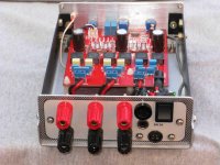
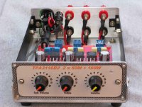
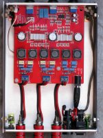
I have just finished putting one of the TPA3116D2 2.1 ebay boards in a case.
The performance, even without any modifications, seems to be very good and at $20 (£13.50) including delivery to the UK it is a real bargain.
The case 1 used originally housed a parallel printer switch. With a new front and back panel it was just the right height and width but it was little too deep.
The extra space was left at the back of the case for any extra decoupling electrolytics across the power supply but the on board ones seem to be adequate.
Running from a 24V bench power supply the current peaked at about 1.5A with the volume cranked up to be quite loud and everything ran very cool. Even at 12V the output was more than adequate.
I'll see how it performs for a while and if no extra bits are required I can reduce the depth of the case by about 40mm. The on board power connector will be removed and wired directly to the switch. I didn't modify the board at this stage just in case there was a problem.
Attachments
John8,
Very nice work there - super clean and professional looking. Love the re-use of an old printer switcher box - in fact I think I have one somewhere and this is a perfect app for it. What kind of input connector are you using - is it a 3.5 mm stereo jack on the back?
X
Very nice work there - super clean and professional looking. Love the re-use of an old printer switcher box - in fact I think I have one somewhere and this is a perfect app for it. What kind of input connector are you using - is it a 3.5 mm stereo jack on the back?
X
The input is a 3.5mm stereo jack socket under the fuse-holder. The back panel was getting full with the speaker terminals so there was no room for phono sockets. I left plenty of space around the speaker terminals to give clearance for connecting the wires.
The 24V power supply I had was fitted with a 4 pin DIN power plug so I had to modify a PCB mounted socket to make it chassis mount.
The 24V power supply I had was fitted with a 4 pin DIN power plug so I had to modify a PCB mounted socket to make it chassis mount.
thanks for guidance!
Dannz for some reason I can't get those links to work.
Search in eBay for zoe_tsang seller and Look for YJ 5pcs high quality audio cable.
Last edited:
John8,
Nice job. May I suggest that you bypass the on board (pcb) 2.1/2.5mm power connector, solder wires from panel conns, directly to the pcb. I guess you could use one of those screw terminals (spkr) as well, if it would fit.
Banana jacks (5 way binding posts) are great for spkrs & power. Did you space them out at 0.75"? for a dual plug?
- Home
- Amplifiers
- Class D
- TPA3116D2 Amp