Hi X- I buy boards and kits from Sure because PE shipping to Canada is too expensive. I love the way Sure package there products.
I assumed that the seller "Sure-Hifi" on Ebay was direct from Sure...
Either way, I've bought a bunch through them and the service has always been excellent and the shipping was free. Very fast shipping.
I agree Sure's packaging is top notch. Anti static bags, foam, nice shiny custom cardboard box good enough for a gift presentation. Someone at PE ought to open up a field office in Canada - they would make a fortune in increased business with reduced shipping.
Hi X- I buy boards and kits from Sure because PE shipping to Canada is too expensive. I love the way Sure package there products.
I did exactly the same thing when I bought the TPA3123 kit - shipping from PE is way high as compare to that of SURE.
Regards,
I assumed that the seller "Sure-Hifi" on Ebay was direct from Sure...
Either way, I've bought a bunch through them and the service has always been excellent and the shipping was free. Very fast shipping.
As far as I know - yes. I like dealing with them.
Regards,
This thread is so huge now it is tough to find specific info. Has anyone changed the gain on the danzz-designed YJ blue board so that it is no longer at the stock "compromise" setting and is more specific to tablets, iphones, etc.?
I am running mine near field and using a tablet or laptop and will probably never use a 2v input from a cd player or AVR as a pre and thus I would like to set the gain for this specific application.
everybody says "just change the resistors" and they note this: "The gain of the TPA31xxD2 family is set by the voltage divider connected to the GAIN/SLV control pin. Master or Slave mode is also controlled by the same pin. An internal ADC is used to detect the 8 input states. The first four stages sets the GAIN in Master mode in gains of 20, 26, 32, 36 dB respectively, while the next four stages sets the GAIN in Slave mode in gains of 20, 26, 32, 36 dB respectively. Table 1 in the data sheet shows the recommended resistor values and the state and gain"
While the data sheet says R1 and R2 control gain/slave settings, I am unsure where these parts are located--other than that on the yj blue board "they are close to the input terminals."
I see that two of the SMD resistors near the chip are marked 100k, and the data sheet says that some of the resistors involved in setting the gain/slave are supposed to be 100k for the 26db and 32 db gain setting.
But, the two through hole resistors near the terminal input block are slightly different to my eyes, and thus might be the ones involved here.
According to the original PCB layout posted by Danzz, it looks to me like the resistors by the input block are NOT the gain setters and that the SMD parts nearest the chip are r1 and r2--and one of them is acutally under the heat sink very close to the chip, that's a deal breaker.
But, the yj board production board is slightly different than the Danzz layout.
I am not going to go further unless I am actually able to do the task. No way I can work SMD given my ham-handedness with the soldering iron. I had a helluva time just removing the main 25v power caps and replacing them with 35v ones--because I am running a 24v power supply.
So, if anyone done this mod, would you post a jpeg or something illustrating which resistors/parts need to be changed specifically on the yj 2.0 blue/black Danzz designed board?
Or, could you just confirm that r1 and r2 are SMD and to replace them you must remove heat sink to get to one of the resistors?
Is there any hope of a noob changing them if they are SMD? I can do speaker crossovers, wiring, shielded RCA interconnects, etc. I have changed the power caps on my yj blue board, rigged up an SMPS, an alps pot, etc. But I have never worked with SMD parts before
Last edited:
Post #1469 and #941 might help if you compare with your board and TI.
The 1uF input caps might limit bass with higher gain selection
The 1uF input caps might limit bass with higher gain selection
This thread is so huge now it is tough to find specific info. Has anyone changed the gain on the YJ blue board so that it is no longer at the stock "compromise" setting and is more specific to tablets, iphones, etc.?
I am running mine near field and using a tablet or laptop and will probably never use a 2v input from a cd player or AVR as a pre and thus I would like to set the gain for this specific application.
everybody says "just change the resistors" and they note this: "The gain of the TPA31xxD2 family is set by the voltage divider connected to the GAIN/SLV control pin. Master or Slave mode is also controlled by the same pin. An internal ADC is used to detect the 8 input states. The first four stages sets the GAIN in Master mode in gains of 20, 26, 32, 36 dB respectively, while the next four stages sets the GAIN in Slave mode in gains of 20, 26, 32, 36 dB respectively. Table 1 in the data sheet shows the recommended resistor values and the state and gain"
While the data sheet says R1 and R2 control gain/slave settings, I am unsure where these parts are located--other than that on the yj blue board "they are close to the input terminals."
I see that two of the SMD resistors near the chip are marked 100k, and the data sheet says that some of the resistors involved in setting the gain/slave are supposed to be 100k for the 26db and 32 db gain setting.
But, the two through hole resistors near the terminal input block are slightly different to my eyes, and thus might be the ones involved here.
No way I can work SMD given my ham handedness with the soldering iron.
So, I am hoping that for the YJ blue board this means the two actual through hole resistors right between the stand off mounting holes in between the chip and the input terminal block are R1 and R2?
If that is the case, I can figure out the rest from the data sheet, but would like to know that those are the only parts that must be changed to alter gain setting--or if a cap needs replaced, that all the parts for this mod are through hole NOT SMD.
I am not going to go further unless I am actually able to do the task.
So, if anyone done this mod, would you post a jpeg or something illustrating which resistors/parts need to be changed specifically on the yj 2.0 blue/black Danzz designed board?
I cannot seem to find Danzz's original pcb layout in the thread.
I'm going to prescribe some tough love because this thread is only going to get longer and it is far from the longest thread on this forum to boot:
You can do a search in the upper right corner for 'gain resistor' or '100k resistor' etc and I bet you would find your answer in the results.
Also if you are going to be modding now is as good a time as any to learn resistor color codes
Or if you are lazy like me simply bend the resistors a little to the side and you will see the value printed on the board beneath them.
You have to be willing to do your own homework on basic stuff like that.
sorry, I was researching and editing/writing at the same time.
let's narrow this down.
On the danzz-designed yj blue/black board 2.0 where are r1 and r2 located?
I can handle the rest.
let's narrow this down.
On the danzz-designed yj blue/black board 2.0 where are r1 and r2 located?
I can handle the rest.
On another forum rhing and others have independently confirmed TenTec/Astron linear power supplies as excellent options for TPA amps. They are kind of expensive new but there are plenty of used options. Made for Ham radio they appear to be extremely robust and high quality with two serious testers claiming they beat out all other PS options tried including batteries.
Look forward to getting one myself soon.
Look forward to getting one myself soon.
Last edited:
sorry, I was researching and editing/writing at the same time.
let's narrow this down.
On the danzz-designed yj blue/black board 2.0 where are r1 and r2 located?
I can handle the rest.
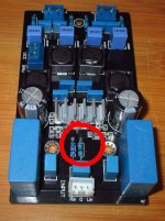
Right in front of the inputs. YJ specifically made them through holes so that they can be changed easily.
Bend them to the side and you will see the value printed on the board as I said above.
alright, thank you.
#1469 shows the prototype Danzz pcb layout, but r1 and r2 on there are slightly different from the production board.
Unfortunately, they are SMD and one of them is under the chip heat sink. may be beyond my skillsz at the moment.
I have a couple of the hiamplifier small green boards coming. With that layout the slave/sync pin is more exposed and it looks like the resistors are all through hole. perhaps I will be able to work on that if gain adjustments are needed.
oh, well #1469 says those two through hole resistors are r12 and r13. maybe I am not reading this correctly?
I thought r1 and r2 were the gain/slave setting resistors?
I thought r1 and r2 were the gain/slave setting resistors?
alright, thank you.
#1469 shows the prototype Danzz pcb layout, but r1 and r2 on there are slightly different from the production board.
Unfortunately, they are SMD and one of them is under the chip heat sink. may be beyond my skillsz at the moment.
I have a couple of the hiamplifier small green boards coming. With that layout the slave/sync pin is more exposed and it looks like the resistors are all through hole. perhaps I will be able to work on that if gain adjustments are needed.
?
The two gain resistors on the YJ blue board are right in front of the inputs. You can change them easily. This is why I linked the color code and mentioned bending them to the side. Either way would have confirmed their values and you would realize they match the gain resistor settings for 26db on the TI datasheet.
Last edited:
so sorry, just went back. Data sheet says "r1 and r2" are controlling gain/slave and connected to pin 8 of chip.
Clearly when you look at danzz board layout the two resistors marked r12 and r13 are connected to pin 8 and they are the through holes.
So, to answer my own question, yes, the through holes at r12 and r13 are the two resistors. they are easily swapped out.
Just because parts are identified one way on the data sheet, does not mean that is how they are identified on the production board.
Sorry for wasting every one's time.
I appreciate the help and response nonetheless.
history major here, last time I did any electronics work it was 8th grade shop class, circa 1979, and I was soldering a digital led clock kit.
Last edited:
so sorry, just went back. Data sheet says "r1 and r2" are controlling gain/slave and connected to pin 8 of chip.
Clearly when you look at danzz board layout the two resistors marked r12 and r13 are connected to pin 8 and they are the through holes.
So, to answer my own question, yes, the through holes at r12 and r13 are the two resistors. they are easily swapped out.
Just because parts are identified one way on the data sheet, does not mean that is how they are identified on the production board.
Sorry for wasting every one's time.
I appreciate the help and response nonetheless.
Lol, you're not wasting people's time per se. But let's say no one answered your question right away or it got ignored (which will happen as the thread lengthens). If you used the color code link or bent them to the side you would have gotten your answer.
didn't want to bend them, and, it's not a question of being too lazy to look up color codes, it's a question of my eyes being so old at this point I cannot tell brown from orange, gold from yellow, black from blue.
and, besides that, I was just confused as to the actual position of the parts--because as noted above the data sheet, which I had in front of me, said gain was set by r1/r2 but the pcb payout, which I was also looking at once I found it within the thread again, has the gain resistors designated as r12/r13.
Once i realized it was better to trace the proper pin on the chip to the parts--in this case pin 8 controls the gain/slave settings, it became apparent that the data sheet designations were not the same as on the board.
r1/r2 for Ti = r12/r13 for danzz yj board.
lesson learned.
next time I will just look at the pins to figure out which parts do what on the board.
Has anyone changed the gain on the danzz-designed YJ blue board so that it is no longer at the stock "compromise" setting and is more specific to tablets, iphones, etc.?
These two resistors set the gain.
Attachments
question to those who own both yj red and blue:
how would discribe the difference between them soundwise?
without volume pot on the red?
how would discribe the difference between them soundwise?
without volume pot on the red?
Ti datasheet and description schematics at gain chapter also confusing🙂 Remember which was 20k and you will be fine
Ti datasheet and description schematics at gain chapter also confusing🙂 Remember which was 20k and you will be fine
they could have written all information in one single table.
but in general the ti-docs seem to be quite good.
learned a lot from them in the last few months.
- Home
- Amplifiers
- Class D
- TPA3116D2 Amp