Good morning,
I have 2 tpa3116 modules from different sources.
One has a Mute connector provided, but with no connecting info.
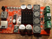
Another has a USB reader and no Mute
None will work. Outputs keep silent.
I know the Outputs are not GND connected and kept them well separated from Gnd.
Any idea what is wrong ? Are they so very fragile that they die at a mere glance ?
Pwer: 0-20V
input: from Generator or USB
Thanks a lot for your help !
I have 2 tpa3116 modules from different sources.
One has a Mute connector provided, but with no connecting info.
Another has a USB reader and no Mute
None will work. Outputs keep silent.
I know the Outputs are not GND connected and kept them well separated from Gnd.
Any idea what is wrong ? Are they so very fragile that they die at a mere glance ?
Pwer: 0-20V
input: from Generator or USB
Thanks a lot for your help !
Please post a couple of photos as requested by norazmi.
Do you have an oscilloscope?
Do you have a Digital MultiMeter?
I know Senlis - last chance to avoid the traffic around Paris.
Do you have an oscilloscope?
Do you have a Digital MultiMeter?
I know Senlis - last chance to avoid the traffic around Paris.
Hello FauxFrench
I have some decent equipment: Rigol 200 mhz DSO, Hameg 2*20 Mhz Analog scope, about 6 multimeters, plus all sorts of generators etc.
What pictures do you want ?
The outputs of this TPA are not grounded, Maybe I shorted the Output when trying to measure something... Which I could not do finally. A square signal comes out as a big "?".
I come from the analog world and it seems that in spite of some strong residual HF wave, the signal on a loudspeaker exists.
Please let me know what pictures you want.
Thanks for the help
Good morning,
I have 2 tpa3116 modules from different sources.
One has a Mute connector provided, but with no connecting info.
Another has a USB reader and no Mute
None will work. Outputs keep silent.
I know the Outputs are not GND connected and kept them well separated from Gnd.
Any idea what is wrong ? Are they so very fragile that they die at a mere glance ?
Pwer: 0-20V
input: from Generator or USB
Thanks a lot for your help !
What is the DC level on the MUTE pin (#12)? If positive it's in mute mode and the outputs go Hi-Z though
I have no guess as to what the DC value of the outputs will be in mute. I use TPA-3116 for my TV but have
never used the mute function of the TPA. During normal operation the output DC will be 1/2 of the power
supply but being BTL, does not require blocking caps on the outputs.
G²
Hello FauxFrench
I have some decent equipment: Rigol 200 mhz DSO, Hameg 2*20 Mhz Analog scope, about 6 multimeters, plus all sorts of generators etc.
What pictures do you want ?
The outputs of this TPA are not grounded, Maybe I shorted the Output when trying to measure something... Which I could not do finally. A square signal comes out as a big "?".
I come from the analog world and it seems that in spite of some strong residual HF wave, the signal on a loudspeaker exists.
Please let me know what pictures you want.
Thanks for the help
Fine gear, that should absolutely do the job.
When you measure on the output of such a BTL-coupled class D amplifier, you connect the scope GND to amplifier "-" (minus) and the probe to one of the two output lines (per channel). Eventually you use both scope probes, one for each output line. NEVER scope GND to an output line.
At the output of a TPA3116 board it is normal with some 5Vpp at 400KHz. It is the carrier frequency.
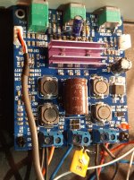
One photo of each of the two boards, please. The TPA3116 is very popular here on the forum. Perhaps we already know the boards.
First test: One board at the time, inputs short-circuited, 8 Ohm resistors as dummy loads on both outputs (stereo), 12-20V supply voltage. The scope GND connected to amplifier board minus supply and the scope probe on each of the four output lines, one after the other. Do you have a 400KHz (almost) triangular-wave signal at any of the output lines?
Here are the photos
Good morning
Here are the photos of the 2 sets I have.
One is integrated in a amp set I am making. It is PWsupplied through a Polyswitch, electronic fuse notes 3A.
It is also tweaked for a delayed 'on', to avoid the "plop" start.
Thanks for your advice.
Good morning
Here are the photos of the 2 sets I have.
One is integrated in a amp set I am making. It is PWsupplied through a Polyswitch, electronic fuse notes 3A.
It is also tweaked for a delayed 'on', to avoid the "plop" start.
Thanks for your advice.
Attachments
Stratus, the DC levels on pins 12 and 2 are checked so the outputs are not HiZ. It has a 100k on board R.
Thanks
Thanks
yes they run at 400khz arround that frequency, can you check at inductor is there is any oscillation and what frequency you get?
Hi Billy,
Many thanks for the photos. They help us a lot because they show that at least the board to the right, but probably also the board to the left, includes more than just a TPA3116 amplifier. With "more" I mean a pre-amp circuit and perhaps other functionality. The board to the right also includes a control-circuit and USB/MP3 decoding. All this "more" may be the reason why the TPA3116 part seems not to work. A TPA3116 chip includes two pins (2/SDZ, 12/MUTE) with which an external circuit can disable the TPA3116 chip. This may be why your amplifiers do not give any sound because the "more" tell the TPA3116 chip to be quiet.
You ask: "Are they so very fragile that they die at a mere glance ?". Yes, if you work in a team with some of these super-heroes having laser- or X-ray sights and you have been staring intensely on the boards. Else, the reason may be more trivial (unfortunately). Such boards are produced out where the salaries are very low and the designs are known frequently to include errors or the boards are produced using wrong components. Many boards seem to have been shipped without proper testing. You are for sure not the first forum member to have problems with such boards.
Billy, are you confined (like I am) until 11 May such that you have time and energy to engage in investigation of the circuits with a good chance of failure?
If you go on with investigation, a TPA3116 chip is only active with pin 2 (SDZ) being high and pin 12 (MUTE) being low. BUT, it is not that easy to measure because the TPA3116 pins are so tiny that you cannot connect a DMM probe without risk of short-circuiting other chip pins. You need to use your Ohm-meter (without supply power to the board) to find out where pins 2 and 12 are connected and at these external points you have a chance to measure the logic levels when the board power is ON.
Are there any situations where pin 2 is high and pin 12 low on any of the boards? If not, you have no chance of sound at the outputs.
Last edited:
Reading this thread with interest. I have seen reference before to checking whether a certain devices pin is "high" or "low" but don't know what this means. Is this high or low resistance?
Hi FauxFrench,
Thanks for the input. Yes I did check on those pins and both are indeed to the proper V level, through somme on board 100K Resistors.
I will investigate further.
I have downgraded the gain to 20dB instead of the 26 dB there was, according to the data sheet.
Still it does not perform as expected, I will go on.
Thanks for your input !
Puffin, by High I mean it is connected to the +Vcc through a 100k Resistor, by Low I mean connected to Gnd via 100K. Those are the values I found on my board.
Puffin, by High I mean it is connected to the +Vcc through a 100k Resistor, by Low I mean connected to Gnd via 100K. Those are the values I found on my board.
Billy, thanks very much for the swift reply. Rob.
- Home
- Amplifiers
- Class D
- tpa3116 trouble