i would like to go with the first option as i dont have to experiment with different component values.
Simming is a good option. It has a fair learning curve to it but it opens up a new world of control over your designs.
You'll need to take measurements, some using a microphone, some electrical, some using two input channels per measurement depending on how you approach it. None is very difficult although there are a few tricks and traps.
Then you need to be able to convert your measurements into useful data files. Some speaker design software will do all the above for you. I like to have my data files separate so I can modify them to my liking but it isn't essential.
Then you need to learn to use a simulator. Some are easy to learn. You'll be able to do in minutes what may otherwise take hours or days.
hi all
i am trying to understand passive crossover design for 3-way speakers. when all three drivers are connected to signal source (amplifier) then how much impedance the amplifier sees? assume all three have 8 ohms of impedance.
thanks,
pranam
Here's what an impedance reaction looks like for a 2 way speaker. The red line is the impedance plot. It can easily be measured with a woofer tester (WT2 or 3). As you can see, it varies quite a bit with frequency.
Attachments
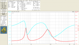
as in the impedance reaction plot as shown above, if the impedance is not 'constant' across frequency band of its operation, then is not xover point will change as the impedance changes? do i only need to consider impedance at xover point and not bother about its value at rest of the band while designing xover network?
as in the impedance reaction plot as shown above, if the impedance is not 'constant' across frequency band of its operation, then is not xover point will change as the impedance changes? do i only need to consider impedance at xover point and not bother about its value at rest of the band while designing xover network?
What you saw in my post was a SYSTEM impedance of a speaker. What you want is the impedance plot of the individual drivers. Then you can pick off those plots the impedence value at your xover point of choice and plug those values into your xover calculations.
Re:’please point me to a good tutorial for designing passive xover networks’:
Passive Crossover Network Design
re:'do i only need to consider impedance at xover point ' - yes
Passive Crossover Network Design
re:'do i only need to consider impedance at xover point ' - yes
Choosing one point is the best you can do unless you take measurements. Which point? ... you will need to follow up until you like what you have. Shown below, you can have good summing at one point but further out, phase issues can cause cancellation. You can also have level issues.
Attachments
- Status
- Not open for further replies.