Looks like an interesting project - I've sent off for boards from JLCPCB, which should arrive in a few weeks. If anybody in Australia wants a board for the price of postage please let me know.
I'll begin collecting parts in the meantime. Any suggestions on where to source the DAC chips, or it is a case of picking a supplier at random on Aliexpress? Similarly, are the coils best bought from Mouser?
I'll begin collecting parts in the meantime. Any suggestions on where to source the DAC chips, or it is a case of picking a supplier at random on Aliexpress? Similarly, are the coils best bought from Mouser?
I could ship you almost any number of DAC chips but I don't get Aliexpress's low shipping rates so yes I think Ali (or eBay) is the best route to the TDA1387s. Coilcraft used to give out free samples but I'm not sure they still do in which case Mouser is a reliable source for inductors.
Ranchu,Looks like an interesting project - I've sent off for boards from JLCPCB, which should arrive in a few weeks. If anybody in Australia wants a board for the price of postage please let me know.
Yes this is an interesting project and Abraxalito certainly has some skill in designing these curcuits.
I have built both Toscanini and Dorati which are quite similar architectures, so I will offer some unsolicited advice.
- The IV on Toscanini is opamp based and has more noise then Dorati.
- The filter I found is very important part of the cicuit and the Dorati has high precision custom wound inductors that Abraxalito makes himself. When I built Toscanini I had to purchase a lot of these standard inductors and measure them to select ones close to the design goals. I built a 2nd Toscanini and Abraxalito made me some of his custom would inductors at a fair price.
- During my build I was getting a lot of hash noise and I couldn't find where it was coming from in the curcuit, after a lot of hair pulling I found the my simple SMPS bench supply was causing it. Hooking it up to a nice linear supply and a quiet amplifier solved the issue. At nearly the same time I was build Dorati and tested it on the same test bensch supply and test amp and it was quiet out of the box. Dorati has better noise rejection, and while you could build some super quiet supplies, I sleep better at night with both quiet supplies and good noise rejection on Dorati.
So my advice is take a look at Dorati, it's better in many ways and can be purchased from Abraxalito for signifanctly less than buying the parts for Toscanini on Mouser, especially if you buy a bunch of coils to select for tight tolerence around nominal.
My mistake was finding Dorati after I had already placed all my part orders...😡
Good luck with your build whichever way you choose.
G
Thanks G, much appreciated.
I'll message Abraxalito to see if he has any leftover Dorati kits for sale. It appears to have a large following of satisfied builders, which is some comfort given that this will be my first DAC build.
I have Toscanini boards and 250 pcs DAC chips on order so I'll likely build both and compare.
I agree that a well regulated and very low noise linear power supply is a must. I've got some LM317 boards that will do for testing but will probably want something better for the finished product.
Ranchu,
Wow! 250 pieces of 1387's you could start your own DAC factory.
I'm not sure your SMD experience level, so please ignore if my suggestions are redundant:
Both of these boards (Dorati and Toscanini) use mostly 0805 passives. These are easy to be done by hand but it is helpful to have a few different tools on hand.
1. Small tip lower wattage soldering iron and stable tweezers.
2. Good lighting at the soldering station.
3. Magnifing lens to check the joints.
I go slow and do a few, then check my work carefully and even then I still occationally make mistakes if my confidence gets too high.
Depending on your experience level it might make sense to practice on one of those Toscanini boards and then do the Dorati. Abraxalito kindly sends a few spares in his kits but it's also pretty easy to send one of those parts flying across the room and you will likley never find it.
G

Thanks G.
The 1387s were incredibly cheap at around 10 cents apiece so it made sense to buy in bulk. Normally I only buy from approved distributers. so fingers crossed these don't turn out to be bad copies.
Fortunately, I use SMT for my own designs, down to 0603 for the passives and small outline semi's, so I should be OK. As you say, good lighting, a jeweller loupe. and a fine tip in a good iron are key, along with a steady hand and a little flux paste on the really fine pitch ICs.
Cheers Christian
Thank goodness for these spare parts! I am busy populating a Kubelik board and had a capacitor flying into the Bermuda triangle last night. First component I lost so far.Abraxalito kindly sends a few spares in his kits but it's also pretty easy to send one of those parts flying across the room and you will likley never find it.
I did not build Toscanini, but did build Dorati and agree with GHarbin. Its a very solid performer, especially at the kit price.
lol, you are far from the only one. Boy, did I appreciate the bonus bits.Thank goodness for these spare parts! I am busy populating a Kubelik board and had a capacitor flying into the Bermuda triangle last night. First component I lost so far.
Imagine how many components are floating around in said triangle.
Hi everyone.
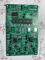
I wanted to share a brief progress update. All the remaining parts have arrived from Mouser and I spent a couple of hours soldering over the weekend. With a bit of luck I should have the board fully stuffed within the next few days and then playing music once I’ve hooked everything up.
I wanted to share a brief progress update. All the remaining parts have arrived from Mouser and I spent a couple of hours soldering over the weekend. With a bit of luck I should have the board fully stuffed within the next few days and then playing music once I’ve hooked everything up.
Attachments
Sorry, a couple more questions.
The receiver card I got from Ali is fitted with jumpers labelled SCKO and DOUT.
SCKO options are 128fs, 256fs, 384fs and 512fs.
DOUT has options for 16bit right justified and 24bit right justified, 24bit left justified and 24bit I2S.
Should I leave it at the default setting of I2S out 256fs?
Thanks a million.
Attachments
No worries, questions are what this thread's for. As well as feedback of course....
I think the SCKO from DIR9001 gets routed to the pin marked 'MCLK' on the header. As this pin isn't used for Toscanini it won't matter at all what the SCKO setting is. Set the output format to I2S, both bits = 1.
I think the SCKO from DIR9001 gets routed to the pin marked 'MCLK' on the header. As this pin isn't used for Toscanini it won't matter at all what the SCKO setting is. Set the output format to I2S, both bits = 1.
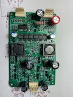
Some progress…
I connected power and flipped the switch on the bench supply to little fanfare; no pops or smoke and the current quickly settled to 130mA. A promising sign.
I then probed all the test points and everything appears to be normal. The outputs are sitting at around 8.1V, which is a little asymmetric and I guess that is what the trimmer resistors are for. I can’t see it being an issue assuming the output is the usual 2Vrms.
The PCB routing is amazing and way beyond the usual standard for DIY. I can only imagine how much skill and effort has gone into this. I
guess the only feedback I have is in relation to the dissipation of the shunt reg dropping resistor (R11) feeding the DAC ICs. It dissipates 560mW which is well within the component ratings but it does get very hot considering it’s very close proximity to the bulk caps. I preempted this during construction, gapped the resistor 6mm off the board and angled it inwards to increase the air gap. I’m not sure how others feel about this in terms of component life.
Next step will be to hook it up to a signal generator and scope. Very excited to have a project back on the workbench after all these years!
That's very useful feedback about the heat from the TH resistor. I must confess I only emulated it by building little towers of 1206 resistors when I was doing the prototyping. One way to reduce the temperature would be to mount two resistors but vertically in place of the single horizontal one. But then the resistor towards the top of the board might heat up the cap nearby even more, even though it would run cooler.
The thermal constraints are really significant for a DAC of this design, where the analog stages need a much higher rail voltage than the DACs themselves. Its what is leading me towards using TDA1545 in newer designs rather than TDA1387 as the former draws lower current for the same output current.
Btw your scribbled voltages on the schematic look well inline with what's I'd expect from a working DAC. Great work so far!
Thanks abraxalito.
The TH resistor is the best choice for this application, IMHO. It allows the part to be stood off the board so as to minimise heating effects on the pcb and surrounding components. This would not be possible with SMD resistor strings or stacked parts.
The heat will probably cause C1 and C2 to dry out prematurely, but there is little that can be done about that without increasing the board size and spacing the components. The alternative, as you say, is to run the digital and analogue stages from separate rails. Apart from improving thermals, a secondary benefit is the analogue stage could be run at the opamp limits (say 30V) to slightly improve linearity. However, I like the way you have designed this because it can be run from a plug pack with a single transformer winding.
I too very much like the convenience of single rail operation. The most recent evolution of this design has an even lower analog rail, 9V to reduce the heat dissipated in the series dropper Rs. Together with using TDA1545s for economy of supply current, it allows many more DAC chips to be paralleled in the pursuit of lower noise : https://www.diyaudio.com/community/...-rbcd-multibit-dac-design.324933/post-7303573
- Home
- Source & Line
- Digital Line Level
- Toscanini NOS DAC