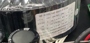
The following amplifier power ratings are as follows:
Do I understand correctly that the toroidal transformer has 3 dual secondary windings, 2 of which are rated for 34 V at 4.5 A, wired in series center tapped to provide 2 x 68 VCT AC to the supply board?
What is the VA rating of the given toroidal transformer?
Thank you kindly!
- 2 x 330 W at 8 ohms
- 2 x 450 W at 4 ohms
- 1 x 900 W at 8 ohms bridged
- I/P:
- 0 -120 V at 60 hz
- O/P:
- 34 V - 0 - 34 V - 4.5 A
- 34 V - 0 - 34 V - 4.5 A
- 25 V - 0 - 25 V - 0.5 A
Do I understand correctly that the toroidal transformer has 3 dual secondary windings, 2 of which are rated for 34 V at 4.5 A, wired in series center tapped to provide 2 x 68 VCT AC to the supply board?
What is the VA rating of the given toroidal transformer?
Thank you kindly!
Attachments
Last edited:
bear in mind that the amplifier power was based on sine wave values, but we listen to music, not sine waves.....
so the rms sine power of our amps will never be the same as with music, some put the ratio of sine power over music power at a factor of ten....
you can take your clue from this.....
so the rms sine power of our amps will never be the same as with music, some put the ratio of sine power over music power at a factor of ten....
you can take your clue from this.....

The VA rating is the voltage multiplied by the current. For multiple windings you add the VA ratings for windings. So in your case: 2*2*34*4.5+2*25*0.5 = 637 VA. That's maybe a little on the small side for a 330 W amp, but should work just fine. As pointed out above, you probably listen to music rather than sine waves and probably also not at clipping levels.
If you connect the windings as you describe and provide 2x68 V to the power supply, you'll end up with around ±90 V rectified. 330 W into 8 Ω is "only" 72.7 V, peak, so I question the need for a ±90 V supply. Is that really the recommended supply voltage for this amp?
Is this an amp that you're building or one that you're reverse engineering?
Tom
Thank you all for answering!
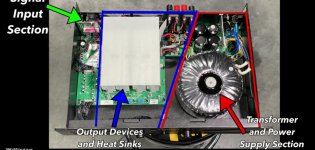
It's a Crown XLI 1500 and I'm trying to understand if the power supply is solid enough for the rated power specified by the manufacturer.
A dyno test published on YouTube revealed that the amplifier is capable to deliver higher power values than the published official ratings.
The amplifier is currently used to drive a pair of 165 W / 6 ohm speakers.
I never use the amplifier to drive speakers rated higher than 200 W continuous.
My estimations, if correct, look something like this:
68 VAC x √2 = 96.166 V peak rectified
96.166 V x (2/π) = 61.221 VDC
Last edited:
IF it´s a quad rail (Class H) amplifier, then max rail voltage is 68*1.4142=+/-95V (considering diode drops)
Raw/Peak voltage drops between 10% (oversized supply) to 20% (skimpy one).
Since this one looks like a beancounter approved amp, let´s consider 20% so we have +/-76V rails, under full load.
Substract 4V each side for transistor drop, we have "useful" 72V peak, so 51V RMS, so possible 325Winto 8 ohm, and bout 50% more into 4 ohm.
Which closely matches official specs.
Transformer VA|rating is just fine for 8 ohm loads, skimpy for 4 ohm ones, but as mentioned above more than enough for Home/HiFi use.
Not so sure under PA/DJ abuse though.
According to Crown, the XLI 1500 is a class AB amplifier.IF it´s a quad rail (Class H) amplifier
If the amp is just a dual rail, then perhaps there are left and right power supplies to justify the existence of four reservoir caps. What doesn't compute though is how, with 63V rated caps, it can deliver 330W into 8R. As @tomchr points out, that requires almost 73V even before output transistor drops, regulation and ripple are accounted for.
A full sine wave only draws 5.7 amps of DC current here. RMS secondary could be up to double that, or maybe 11 amps. Even a woosy 4.5 amp transformer can survive for many minutes, maybe an hour at 11 amps. Those wimpy heat sinks will get hotter than the fires of hell and damnation long before then - fan or no fan. (give it two to five minutes).
Even a DJ turning it up to garbled would only be running about 1/2 to 1/3 power on average. The thermal cutout on the heat sink will cut out first.
Even a DJ turning it up to garbled would only be running about 1/2 to 1/3 power on average. The thermal cutout on the heat sink will cut out first.
The transformer secondaries are rated:
If each of the secondary windings can supply 4.5 A, how is it possible to deliver 450 W at 4 ohm requiring 10.60 A of current?34-0-34 V at 4.5 A
34-0-34 V at 4.5 A
According to the official specifications the amplifier gain is 31 dB.
At an input sensitivity level of 1.4 V RMS and an amplification factor of 35.48 we get the following output voltage level:
1.4 x 10^(31/20) = 49.67 V RMS
Required current at 8 ohm: 49.67 / 8 = 6.209 A
Required current at 4 ohm: 49.67 / 4 = 12.418 A
Power at 8 ohm: 49.67 x 6.209 = 308.42 W
Power at 4 ohm: 49.67 x 12.418 = 616.85 W
Where is the required amperage obtained from?
Last edited:
do the FTC pull power both channels driven tests and resolve all doubts....if it passes, then all is fine...
but bear in mind that even if you get few hundred watts with FTC, playing music will just cost you 5 to 10 watt at average, and at this power, your music can be loud...
but bear in mind that even if you get few hundred watts with FTC, playing music will just cost you 5 to 10 watt at average, and at this power, your music can be loud...
DC current draw (from both channels combined) is 0.637 times the peak current of one channel. At 8 ohms, that’s 9 amps peak or 5.7 amps DC drawn off the supply. The AC RMS secondary current is somewhere around 2X that. (I calculate 12.4A, assuming 65% power factor and 76 volt rails for 72V peak output). Goes even higher with lower Z loads. A lot more than 4.5A you say?
The transformer has less “VA” capacity than the amp power, because when putting out sine waves it is OVERLOADED. These types of transformers will take it for many minutes before there is a problem. Music never draws that kind of power - even a ghetto bass line driven to obvious clipping. They size the transformer to deal with the average load when turned up to obvious clipping, and let it “overload” for short periods of time as needed. Unless you’re being stupid about it, it is harmless. Switch mode stuff will shut down or otherwise limit within a second (sometimes milliseconds) which is why many sound anemic compared to even this low end amp.
FTC test used to have a 1/3 power burn-in for preconditioning, before measuring short term sine wave power. That was reduced to 1/8 power some time ago, and eventually dropped entirely.
And yes, sometimes my use cases are “stupid about it”. I’ll size the transformer accordingly and not expect this out of a lower-tier “prosumer” amp.
Actually, it's (68-1.4) * √2 = 94.2 V, peak, rectified, assuming 700 mV across each rectifier diode. Obviously the voltage across the diodes is temperature dependent, so it may be more like (68-1.0) * √2 = 94.8 V, peak, rectified once the diode bridge has reached operating temperature.68 VAC x √2 = 96.166 V peak rectified
This does not account for the ripple voltage, however, so the DC voltage at the output of the power supply will be lower than the 94 V, peak, rectified.
Typically you'll have around 1.30-1.35 times the applied AC voltage at the output of the supply, under load, so you're looking at 68*1.30 = 88.4 V to 68*1.35 = 91.8 V, under load, depending on the amount of supply capacitance. If you're into solving differential equations you can probably work out an analytic solution. If not, I suggest simulating the circuit to determine the exact output voltage.
Above numbers assume that the transformer provides 68.000 VAC and has zero DC resistance (i.e., is superconductive at room temperature). In reality, production tolerances, mains variation, etc. will result in quite a bit of variability. It's reasonable to assume at least ±5 % variation just in the mains voltage (assuming you're in North America or most places in Europe), so ±10 % variation once all the other factors are considered is not out of line. So now you're looking at something like:
0.9*1.30*68 = 80 V, minimum
1.1*1.35*68 = 101 V, maximum
So expecting ±90 V at nominal mains for a dual supply is pretty reasonable. Specifying the output voltage with five significant digits is silly as you really don't know more than 1-2 digits.
Where does the 2/π factor come from?96.166 V x (2/π) = 61.221 VDC
Tom
- Home
- Amplifiers
- Power Supplies
- Toroidal transformer VA ratings and wiring help