What do you think about using linear regulated PSU (say 32V 3A) to reduce heating (and to increase overall robustness)? I use sensitive loudspeakers, so some power loss is not a problem. Has anybody tried, used or measured?
a loud pop on the right and it was way quieter.. its dead jim, or is it?
i took apart my pa5 and depotted that mystery module (it got pretty hot). didnt took as long as i expected. some heat gunning and careful prying and cleaning afterwards.

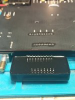
So lets depot it, i got some experience in this from my last project
https://www.diyaudio.com/community/...pair-crackling-popping-on-one-channel.358649/
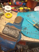
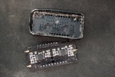
Its a 4 layer PCB...
even ripped off a ressitor as a bonus (which is weird since i didnt put a lot of force and my temp was below 260C. i think it had bad soldering from the factory. one of the possible failure points.)
it consist of
2 NE5532 (outputs are going (via resistors) to the output pins.)
https://www.ti.com/lit/ds/symlink/ne5532.pdf?ts=1665992621095

and
2 OPA1612A (at the input)
https://www.ti.com/lit/ds/symlink/opa1612.pdf?ts=1665988164724
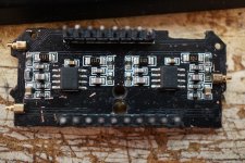
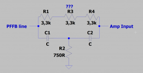
The RC network on each side (top) has the PFFB lines going in and goes to the output pins directly
its literally this.. i didnt found a place where the legs of R3 went other than the reisistors nearby. no connection to the rest of the circuit.
those golden pogo pins are not connected to ground! neither the case has been its anodizing scraped off, its just a snap in retainer (theres small dents in the case) so the potting compoung can flow beneath.
So i put it all back together, obviously without the shielding to see if something is getting hot.
it works again... both channels at the same volume level. weird.
maybe micro degradation of one of those opamps, ne5532 is very reliable, not sure of that opa1612 tho.
or cracked solder joints due to the potting compound contracting/expanding over time.
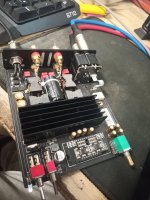
i should have used jumper wires instead, so i can take a thermal photo of the underside.
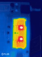
its running great again, sounds like before even without the metal can. lets see how long.
(copy of identical post of me on asr https://www.audiosciencereview.com/...-review-amplifier.28512/page-253#post-1350283 )
i took apart my pa5 and depotted that mystery module (it got pretty hot). didnt took as long as i expected. some heat gunning and careful prying and cleaning afterwards.


So lets depot it, i got some experience in this from my last project
https://www.diyaudio.com/community/...pair-crackling-popping-on-one-channel.358649/


Its a 4 layer PCB...
even ripped off a ressitor as a bonus (which is weird since i didnt put a lot of force and my temp was below 260C. i think it had bad soldering from the factory. one of the possible failure points.)
it consist of
2 NE5532 (outputs are going (via resistors) to the output pins.)
https://www.ti.com/lit/ds/symlink/ne5532.pdf?ts=1665992621095

and
2 OPA1612A (at the input)
https://www.ti.com/lit/ds/symlink/opa1612.pdf?ts=1665988164724

The RC network on each side (top) has the PFFB lines going in and goes to the output pins directly
its literally this.. i didnt found a place where the legs of R3 went other than the reisistors nearby. no connection to the rest of the circuit.

those golden pogo pins are not connected to ground! neither the case has been its anodizing scraped off, its just a snap in retainer (theres small dents in the case) so the potting compoung can flow beneath.
So i put it all back together, obviously without the shielding to see if something is getting hot.
it works again... both channels at the same volume level. weird.
maybe micro degradation of one of those opamps, ne5532 is very reliable, not sure of that opa1612 tho.
or cracked solder joints due to the potting compound contracting/expanding over time.

i should have used jumper wires instead, so i can take a thermal photo of the underside.

its running great again, sounds like before even without the metal can. lets see how long.
(copy of identical post of me on asr https://www.audiosciencereview.com/...-review-amplifier.28512/page-253#post-1350283 )
unless the black potting compound, which causes 40% failure rate so far, affects the sound in any way, then yes it is.
lots of feedback and two gain stages in series.
topping is using different parts from what the Ti document recommends.
instead of R_fb 33k, its using 9.9k (spread over 3x3.3k resistors) and R_fb_gnd is 750 ohms instead of 10k.
lots of feedback and two gain stages in series.
topping is using different parts from what the Ti document recommends.
instead of R_fb 33k, its using 9.9k (spread over 3x3.3k resistors) and R_fb_gnd is 750 ohms instead of 10k.
yup, all parts are reliable on their own but putting them in epoxy or whatever this stuff is + heat cycles causes problems
if someone has a PA5 that failed or wants to prepare in case it may fail someday
i got a few replacement modules left over as seen here https://www.audiosciencereview.com/...-replacement-for-everyone.44219/#post-1572910
no potting, no reason to fail.
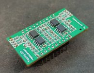
i got a few replacement modules left over as seen here https://www.audiosciencereview.com/...-replacement-for-everyone.44219/#post-1572910
no potting, no reason to fail.

D
Deleted member 148505
I have an unmodified, untouched PA5 here and when I measured it, the THD is only around -70ish dB. 2nd and 3rd harmonic is only around -76dB and -78dB. Other harmonics are below -120dB just like on ASR. The noise is up to spec. Didn’t bother to investigate since the sound is fine.
Either the measured ones were golden samples, or somewhere down the line, they have changed the opamps to cheaper ones, or it might be that the potted module is overheating on the unit that I’m measuring.
Either the measured ones were golden samples, or somewhere down the line, they have changed the opamps to cheaper ones, or it might be that the potted module is overheating on the unit that I’m measuring.
Last edited by a moderator:
PCB layout.With an identical circuit and the same components, why shouldn't it be like this?
Of course, you are right. But you could only say it really reliably if Amirm would measure a working unit, then swap the board and use the same one again. Otherwise you would just have too many variables.
D
Deleted member 148505
I suspect the measurement is lower, around 2dBc to 4dBc difference because of OPA1656 use instead of OPA1612 (if all else being equal). Layout looks good to me
TP RA3 has a 2dBc lower performance than PA5 at 5W 4R, It would be interesting to know the opamp choice.
TP RA3 has a 2dBc lower performance than PA5 at 5W 4R, It would be interesting to know the opamp choice.
Last edited by a moderator:
the current version (the final, single sided one) uses OPA1612 and NE5532 just like the original, my test board in the first topic used 1656 because 1612 were out of stock everywhere and i didnt wanna spend 10 bucks a piece on a greedy supplier for just a prototype, after i knew its working and they went back in stock, i ordered some 1612.
cant edit the first post to clarify that. allways read such threads backwards to get the latest informations.
i also made some boards with four OPA1612 in the past for those who wanted them, i dont think they measure any better but what do i know. better components should perform better
the double sided version only has downsides, more costly to manufacture, heat from top and bottom, not as dense packed as it could be.
the single sided smd version is the way to go, i made a few by now and everyone was happy and never had any issues. still have some more in stock in case anyone needs one.
if anyone wants to send amir a PA5 that has a socket to quickly swap modules, together with a original module and my replacement, do it.
but i dont want to spend a lot of money for shipping and customs and not have mine for weeks.
Even if my module measures a few dB worse in the end, the alternative would be throwing a PA5 away.
Last edited:
Just got my replacement module from gamerpaddy...Thank you Sir! What a pain it was to get the original module off the PCB. As usual these overseas manufacturers use cementium solder requiring a long song&dance with higher soldering station temps, flux paste, low temp melting solder and gentle prying. At least they didn't put glue under the thing as well. Thinking of using risers on the board (with obvious restrictions of max heights allowable) so I can just slide the replacement module in & out. Hope to test it all out in the next few days.
Now on to freeing the original module from its unheavenly bond with resin....will keep me out of trouble.
Cheers
Now on to freeing the original module from its unheavenly bond with resin....will keep me out of trouble.
Cheers
cascading two with little gain improves their performance over having one with a lot of gain.
https://www.ti.com/lit/an/sboa356/s...10413&ref_url=https%3A%2F%2Fwww.google.com%2F
https://www.ti.com/lit/an/sboa356/s...10413&ref_url=https%3A%2F%2Fwww.google.com%2F
- Home
- Amplifiers
- Class D
- Topping PA5 (TPA325X) : Is a modification worth it? ?