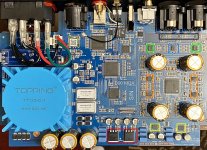
I made a rough sketch of the output stage schematic. Maybe I could dig that up if needed. In the meantime the pic you linked to has been marked up a bit and attached below.
Colored boxes indicate the following:
Red: Vref pre-regulators
Yellow: +-11v opamp rail regulators
Orange: I/V opamps
Green: XLR output and differential summing opamps
Blue: RCA output opamp differential summed from XLR outputs
Black: Analog switches used for muting
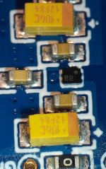
Also a pic of one of the 4 secondary Vref regulators, each of which is located near one of the 4 big electrolytic caps near the AK4499 chip.
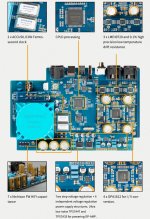
Just found another pic that somebody marked up.
EDIT: Added mute switch data sheet.
Colored boxes indicate the following:
Red: Vref pre-regulators
Yellow: +-11v opamp rail regulators
Orange: I/V opamps
Green: XLR output and differential summing opamps
Blue: RCA output opamp differential summed from XLR outputs
Black: Analog switches used for muting
Also a pic of one of the 4 secondary Vref regulators, each of which is located near one of the 4 big electrolytic caps near the AK4499 chip.
Just found another pic that somebody marked up.
EDIT: Added mute switch data sheet.
Attachments
Last edited:
I opened it. Some pics in #21 above. Mine looks the same as those except no MQA and I have some hi-res pics of the one here. No super long hex drive that I recall. Was recently looking for the output stage sketch, but hasn't turned up yet.
Last edited:

Thanks. I ordered a set yesterday. Hopefully they'll fit. Mine has a short in the DAC VREF circuit. I'm waiting on the thermal cam to locate it.I opened it. Some pics in #21 above. Mine looks the same as those except no MQA and I have some hi-res pics of the one here. No super long hex drive that I recall. Was recently looking for the output stage sketch, but hasn't turned up yet.
The little tiny secondary Vref regulators are BGA. If one of those went bad it may be tricky to repair. The primary Vref regulators are SMD 317 types. This is for the original AK4499 based D90, of course.
Same model here. After taking a closer look at the attached photos my short is in the I/V section. The OPAMP power supply has two separate outputs. One goes to I/V section and the other to the output buffers.
The first image in #21 shows the opamp regulators outlined in yellow color. Voltage is +-11v, probably so as not to overvoltage analog switches using for muting the audio outputs. Not sure what evidence is being seen to suggest I/V and output opamps are powered differently?
- Home
- Source & Line
- Digital Source
- Topping D90 help