Every time I look at that cathode follower, I think, "Is that on purpose?" Terrible source impedance, severely limited swing (less than the CD player output!), high distortion. Absolutely incompetent design for hifi.
Every time I look at that cathode follower, I think, "Is that on purpose?" Terrible source impedance, severely limited swing (less than the CD player output!), high distortion. Absolutely incompetent design for hifi.
I believe it is on purpose!
People who are fooled by Wiki article about tube sound, and other similar ignorant articles, try to "add specific musical tube distortions".
They go for distortions, SY. They believe additional distortion is what we are after.
Every time I look at that cathode follower, I think, "Is that on purpose?" Terrible source impedance, severely limited swing (less than the CD player output!), high distortion. Absolutely incompetent design for hifi.
At least they put the load resistor of CF at "only" 10 (yes, ten - there are originally two tubes in parallel !) times the plate resistance, could have been worse ... like the anode load of first stage (almost 100x Ra 🙄 ).
I kept it down to 2.5-3x Ra as it is obvious that it doesn't have to drive a heavy load (otherwise OP would have complained already).
Wavebourn nailed it spot on.
Arnulf, can you tell me why R3 is included?
I've noticed this on other amps just after the pot too..
I've noticed this on other amps just after the pot too..
At least they put the load resistor of CF at "only" 10 (yes, ten - there are originally two tubes in parallel !) times the plate resistance, could have been worse ...
It actually IS worse. At the trickle current that they've biased the CF, the plate resistance is very, very high.
Arnulf, can you tell me why R3 is included?
I've noticed this on other amps just after the pot too..
It's to protect the preamp against the likely eventuality of the wire-to-track connection in the pot getting intermittent or going open.
dont need the coupling cap? dont i want to isolate the dc voltage of the first stage from the second and allow the signal to pass?
I am feeling blunt today. Please do not take offence.replacing the 220k with a 100k means that there will be less voltage across that resistor and more across the tube. is this right? wont this increase the gain? i dont know.
First, redraw your schematic. Notice Arnulf drew his with input on the left, output on the right, ground on the bottom and B+ at the top. This allows you to identify the individual stages.
Second, gain is not directly determined by the voltage across the tube.
Gain, or Av approaches the Mu of the tube as the plate resistor approaches infinity for a grounded cathode stage. Your first stage is a grounded cathode by the way.
Lowering the Plate resistor, reduces gain but increases distortion. The Mu of a 6N1P is about 40 and the Rp (internal tube resistance) is about 9K ohms.
If you want to learn about this, there are some appropriate resources.
Morgan Jones "Designing Valve Amplifiers" is the on I have.
I know people also recommend several on line resources as well.
HTH
Doug
It actually IS worse. At the trickle current that they've biased the CF, the plate resistance is very, very high.
Wait, I lied, common cathode load is not 100x Ra per tube, it's mere 45x Ra oper tube 😀
I have a feeling this circuit was designed with 6N2P in mind. Everything would make much more sense in that case ... except the paralleled tubes, of course.
@Globulator: SY explained it already, I'll just add some further clarification regarding its choice: the resistor R3 isn't supposed to affect the input, hence significantly larger resistance compared to to R1. It is essentially in parallel with lower section of R1. When R1 breaks down mechanically (potentiometers have this nasty habit), R3 will prevent grid voltage from floating up and tube selfdestructing itself.
Now in theory - if grid had unlimited power dissipation capability (well, least as high as maximum cathode emission) - grid would stabilize at some potential eventually due to constant flow of electrons from the cathode and inherent feedback action of electron repulsion/attraction based on terminal (in this case terminal = grid) potential. Thing is, grid just might not survive long enough to stabilize, or alternatively, it might not survive after stabilizing itself either - it's usually just not designed for grid current operation and this is usually reflected in datasheet either directly (by Ig specification) or indirectly (by specifying upper limit of Rg - the higher it is, the more leeway there is usually).
Would schematic help ? I drew one just for you. Unlike what you've got there it's actually suited to 6N1P tubes and shouldn't be just a distortion box. If you intend to keep the silly double tube with shared load resistor arrangement, halve the values of R4 and R7 (each tube sees same load so when paralleled, the combined load is 1/2 the load of a single tube).
This assumes supply voltage V+ of 200-300V.
I just noticed a typo: "at keast" should of course be "at least" 🙄
As for replacing R8 with green LED (which should improve gain and probably sound better): make sure you buy the cheapest example of low luminance low current matte dome kind that is avaliable to you (the more expensive high luminance bright green types have considerably higher Vf and will again bias the first stage waaay into non-linear region). LED must light up when circuit is turned on - if it doesn't, you've got its polarity wrong and you must reverse it.
first of all thanks very much for taking the time to draw this schematic.
some elementary questions about this schematic. this looks like a completely different design. im a neophyte caught between the diametricaly opposed opinions of established experts. my question is how can the design be that bad if the person who designed it has a recognized name in the audio industry, designs amps and speakers, has his own design of transformers manufactured for him etc. im sure you understand my confusion.
as for the schematic. it looks like you have completely redesigned the entire preamp. are the cathode followers that bad? V1 and V2 are two seperate tubes but each of them contain two triodes. so i assume that this design abandons the idea of using both of them in a paralleled conformation. if this is true is it possible to use one tube for both these gain stages instead of two seperate tubes?
what would the value of C1 be?
what would the value of C3 be if the power supply is bad and what do you mean by a psu that sucks. lol
so i guess i need to completely rewire the whole thing eh? keep the leads as short as possible, run the wires close to the chassis.
i have to learn more about mu, gain and plate resistance and interelectrode capacitances and rf interference and feed back etc. joy of joys, dream of dreams
thanks again very much the schematic. i have a protoboard that i am going to lay it out on.
all the resistor values are 1/2 watt unless otherwise stated?
Last edited:
Wait, I lied, common cathode load is not 100x Ra per tube, it's mere 45x Ra oper tube 😀
I have a feeling this circuit was designed with 6N2P in mind. Everything would make much more sense in that case ... except the paralleled tubes, of course.
@Globulator: SY explained it already, I'll just add some further clarification regarding its choice: the resistor R3 isn't supposed to affect the input, hence significantly larger resistance compared to to R1. It is essentially in parallel with lower section of R1. When R1 breaks down mechanically (potentiometers have this nasty habit), R3 will prevent grid voltage from floating up and tube selfdestructing itself.
Now in theory - if grid had unlimited power dissipation capability (well, least as high as maximum cathode emission) - grid would stabilize at some potential eventually due to constant flow of electrons from the cathode and inherent feedback action of electron repulsion/attraction based on terminal (in this case terminal = grid) potential. Thing is, grid just might not survive long enough to stabilize, or alternatively, it might not survive after stabilizing itself either - it's usually just not designed for grid current operation and this is usually reflected in datasheet either directly (by Ig specification) or indirectly (by specifying upper limit of Rg - the higher it is, the more leeway there is usually).
the schematic states cleary that the design is for 6n1p, 6922 or 6dj8 tubes
the schematic states cleary that the design is for 6n1p, 6922 or 6dj8 tubes
But values fit better 6N2P or 6SL7.
my question is how can the design be that bad if the person who designed it has a recognized name in the audio industry, designs amps and speakers, has his own design of transformers manufactured for him etc. im sure you understand my confusion.
Indeed I do understand. But the high end audio biz is filled with bad design- this is not unique. Some of the bad designs sell for megabucks and get rave reviews in magazines (which tells you how seriously to take reviews in magazines!). I've often observed that you're FAR more likely to get an incomptently designed amp at $20,000 than at $500.
On the bright side, you didn't pay $20,000.😀
whahahahahahahaha! 😕😕😕😱😱😱 and i didnt spend 8000 dollars on speaker cable either🙄
To fully appreciate the poor sound you can buy at almost limitless price try visiting a hi-fi show.
The worst system I ever heard was murdering the track 'Money' by Pink Floyd with £38k of solid state amplification and £18k of speakers. Thin, harsh, compressed, dead. Awful.
Then you get cable demos, some systems sound awful, some systems sound reasonable, in all cases I failed to detect any difference when they change any cable.
It always seems to be the simpler mid range systems that sound the best - perhaps because there is enough money to buy decent bits, and not enough to go completely off the rails and go off focus 😉
If you look at the schematic of his flagship amp (zen) you'll notice the 6n1p load line stays too at the bottom of the curves. This time with a reasonable load (47k) but also with insufficient current. Guess he has found the tube's sweet spot. 🙂
some elementary questions about this schematic. this looks like a completely different design.
No, it is identical (common cathode section followed by a cathode follower section), except that it only uses one tube for each position rather than two in parallel because it isn't necessary to use two, and that it is actually running the tube at the point where it is more linear, where it gives less distortion. Don't worry, there should still enough THD present to make it a bona fide "tube sound"ing preamp 🙂
my question is how can the design be that bad if the person who designed it has a recognized name in the audio industry, designs amps and speakers, has his own design of transformers manufactured for him etc. im sure you understand my confusion.
Beats ne. I'm giving you my honest help at zero cost and I'm posting everything in a public forum for everybody to see where it will be scrutinized by dozens of people who are just as competent. If I wanted to peddle some snake oil to you this would be a really bad way to go about it

If you take time to learn how tubes work, and then compare your existing schematic with mine (while peeking at 6N1P datasheet for operating details, of course), you will notice that everything we've been telling you is true - your schematic shows a distortion box (not of the electric guitar effect kind, just a simple sound mangler), and not a preamplifier. It could be that you've drawn it incorrectly, or that you read the values wrong, it just doesn't fit what anybody here would consider to be a real pre-amplifier ...
as for the schematic. it looks like you have completely redesigned the entire preamp. are the cathode followers that bad?
No, the circuit is the same. You might be confused due to absence degeneration resistor at the anode of cathode follower stage (yet another mistery for me as it only impairs sound further) from my schematic, but this is what cathode follower is - cathode follows grid voltage, there is no need for that resistor in your case.
There is absolutely nothing wrong with cathode follower topology, it is a good circuit and it has its uses. In your case its use is to prevent the loading of first (common cathode) section, which would occur with just about all commercial amplifiers the way your schematic is drawn. In other words: tube operation point wouldn't be stable at all you'd get different results with each different amplifier.
V1 and V2 are two seperate tubes but each of them contain two triodes. so i assume that this design abandons the idea of using both of them in a paralleled conformation. if this is true is it possible to use one tube for both these gain stages instead of two seperate tubes?
6N1P are twin triodes. Since my Eagle tubes library doesn't contain a model of 6N1P yet I used the generic triode model (hence no heater connections or pin names) which results in two different tube names (V1 and V2), even though these could very well be two sections of the same tube. If I used a propper 6N1P model instead, they would have been marked as V1A and V1B. I'm sorry if this caused any confusion, those needn't be two separate tubes (glass bottles).
The way I see it you have three choices:
1: Keep paralleled tubes arrangement. I would only do this if I already had the enclosure and it already had 4 sockets mounted and if I really wanted to use all 4 tubes. Otherwise I'd stick with a single tube per channel.
2a: Use only two tubes for both channels, one per channel, first section of each tube as first stage and second section as second stage. I would pick this option if I were you as it shortens the wiring between sections.
2b: Use only two tubes for both channels, relegating one tube to input duty and the other to output duty. I wouldn't pick this option because it means longer wiring and (if you decide to use lower resistor in cathode follower stage) more power consumption in one of the tubes.
Ultimately, the choice is yours. You mention protoboard further down in your message, option 2a is also easier to protoboard than the other two on top of everything else.
what would the value of C1 be?
Your schematic doesn't even show an input capacitor. Generally any audio equipment which might have some DC present at its output includes a coupling capacitor as well. If potentiometer doesn't make a scratching sound when you turn the volume up or down while your current circuit is playing, you don't need C1, because it would be in series with Cout of your signal source which might lead to undersired HP filtering at the top of audio band (depending on the value of C1 and Cout of your signal source). 100-220 nF value of C1 is just as sane as anything in the neighborhood of that. Use foil capacitor.
what would the value of C3 be if the power supply is bad and what do you mean by a psu that sucks. lol
We haven't seen your power supply unit (PSU) schematic so we can't tell whether it is just as hookey as the rest of the circuit or not. If it is good (= you don't get any mains hum at the output with input shorted together), then you don't need them.
Electrolytics at the anodes need to be of high voltage type (if your supply is 250V, use 300+V types). Something along the lines of 47-100 uF per tube would be just fine.
i have to learn more about mu, gain and plate resistance and interelectrode capacitances and rf interference and feed back etc. joy of joys, dream of dreams
There are plenty of webpages and books that explain tube operation and tube circuit design, Google is your friend. It might seem overwhelming at the beginning but eventually there's always that "Eureka!" moment when all the pieces just snap together and everything starts making sense 🙂
all the resistor values are 1/2 watt unless otherwise stated?
In my schematic ? Yes, if you stick with one tube per channel plan. If you decide to use two tubes in parallel per channel as in your original design, you will have to double the wattage rating of both load resistors the values of which you are halving as the current through them doubles and P = U * I. Double the current, double the dissipation: elementary school physics 😉 If worried, use 2W for load resistors (I calculated 30% safety margin).
Here are few more tips if you happen to have a multimeter handy.
1: Measure your supply voltage. I assumed it was 250V, this might not be exactly the case. Resistor values were calculated according to this assumption and while they are much closer to what they should be than in your schematic, they might still need some tweaking if your supply voltage deviates significantly from this. For example, if you measured your supply to be only 180V, you may need to reduce R4 (and R7) a bit, but don't go below 24K with R4. If supply measures much higher, you can increase thoee resistors.
2: Measure voltage at the anode of first section, it should be within 30-70% of your supply voltage. If it is lower than bottom margin, increase R8 to next standard value. If it is higher than top margin, reduce R8. Ideally this voltage should be around 50% or in slightly less than 50% of supply voltage, but read next paragraph before changing it because it is extremely important.
3: Measure voltage at the cathode of the first section, it should be a couple of volts and no less than say 1.5V. Since we don't know what your signal source is (or its voltage swing, to be more precise), I don't want you to risk driving the tube too close to 0V grid voltage just in case. Something like 2V would be ideal, the least distortion while still operating well away from grid current area.
4: Remember that protoboards (the plastic thingies with lots of holes in them and conductive connections on the bottom side) introduce extra capacitance to connections. It can cause tubes to oscillate and it will mostlikely result in more noise pickup than the actual circuit will exhibit.
5: Don't forget that you're dealing with lethal voltages so exercise due caution.
Happy prototyping !
Last edited:
No, it is identical (common cathode section followed by a cathode follower section), except that it only uses one tube for each position rather than two in parallel because it isn't necessary to use two, and that it is actually running the tube at the point where it is more linear, where it gives less distortion. Don't worry, there should still enough THD present to make it a bona fide "tube sound"ing preamp 🙂
Beats ne. I'm giving you my honest help at zero cost and I'm posting everything in a public forum for everybody to see where it will be scrutinized by dozens of people who are just as competent. If I wanted to peddle some snake oil to you this would be a really bad way to go about it
If you take time to learn how tubes work, and then compare your existing schematic with mine (while peeking at 6N1P datasheet for operating details, of course), you will notice that everything we've been telling you is true - your schematic shows a distortion box (not of the electric guitar effect kind, just a simple sound mangler), and not a preamplifier. It could be that you've drawn it incorrectly, or that you read the values wrong, it just doesn't fit what anybody here would consider to be a real pre-amplifier ...
No, the circuit is the same. You might be confused due to absence degeneration resistor at the anode of cathode follower stage (yet another mistery for me as it only impairs sound further) from my schematic, but this is what cathode follower is - cathode follows grid voltage, there is no need for that resistor in your case.
There is absolutely nothing wrong with cathode follower topology, it is a good circuit and it has its uses. In your case its use is to prevent the loading of first (common cathode) section, which would occur with just about all commercial amplifiers the way your schematic is drawn. In other words: tube operation point wouldn't be stable at all you'd get different results with each different amplifier.
6N1P are twin triodes. Since my Eagle tubes library doesn't contain a model of 6N1P yet I used the generic triode model (hence no heater connections or pin names) which results in two different tube names (V1 and V2), even though these could very well be two sections of the same tube. If I used a propper 6N1P model instead, they would have been marked as V1A and V1B. I'm sorry if this caused any confusion, those needn't be two separate tubes (glass bottles).
The way I see it you have three choices:
1: Keep paralleled tubes arrangement. I would only do this if I already had the enclosure and it already had 4 sockets mounted and if I really wanted to use all 4 tubes. Otherwise I'd stick with a single tube per channel.
2a: Use only two tubes for both channels, one per channel, first section of each tube as first stage and second section as second stage. I would pick this option if I were you as it shortens the wiring between sections.
2b: Use only two tubes for both channels, relegating one tube to input duty and the other to output duty. I wouldn't pick this option because it means longer wiring and (if you decide to use lower resistor in cathode follower stage) more power consumption in one of the tubes.
Ultimately, the choice is yours. You mention protoboard further down in your message, option 2a is also easier to protoboard than the other two on top of everything else.
Your schematic doesn't even show an input capacitor. Generally any audio equipment which might have some DC present at its output includes a coupling capacitor as well. If potentiometer doesn't make a scratching sound when you turn the volume up or down while your current circuit is playing, you don't need C1, because it would be in series with Cout of your signal source which might lead to undersired HP filtering at the top of audio band (depending on the value of C1 and Cout of your signal source). 100-220 nF value of C1 is just as sane as anything in the neighborhood of that. Use foil capacitor.
We haven't seen your power supply unit (PSU) schematic so we can't tell whether it is just as hookey as the rest of the circuit or not. If it is good (= you don't get any mains hum at the output with input shorted together), then you don't need them.
Electrolytics at the anodes need to be of high voltage type (if your supply is 250V, use 300+V types). Something along the lines of 47-100 uF per tube would be just fine.
There are plenty of webpages and books that explain tube operation and tube circuit design, Google is your friend. It might seem overwhelming at the beginning but eventually there's always that "Eureka!" moment when all the pieces just snap together and everything starts making sense 🙂
In my schematic ? Yes, if you stick with one tube per channel plan. If you decide to use two tubes in parallel per channel as in your original design, you will have to double the wattage rating of both load resistors the values of which you are halving as the current through them doubles and P = U * I. Double the current, double the dissipation: elementary school physics 😉 If worried, use 2W for load resistors (I calculated 30% safety margin).
Here are few more tips if you happen to have a multimeter handy.
1: Measure your supply voltage. I assumed it was 250V, this might not be exactly the case. Resistor values were calculated according to this assumption and while they are much closer to what they should be than in your schematic, they might still need some tweaking if your supply voltage deviates significantly from this. For example, if you measured your supply to be only 180V, you may need to reduce R4 (and R7) a bit, but don't go below 24K with R4. If supply measures much higher, you can increase thoee resistors.
2: Measure voltage at the anode of first section, it should be within 30-70% of your supply voltage. If it is lower than bottom margin, increase R8 to next standard value. If it is higher than top margin, reduce R8. Ideally this voltage should be around 50% or in slightly less than 50% of supply voltage, but read next paragraph before changing it because it is extremely important.
3: Measure voltage at the cathode of the first section, it should be a couple of volts and no less than say 1.5V. Since we don't know what your signal source is (or its voltage swing, to be more precise), I don't want you to risk driving the tube too close to 0V grid voltage just in case. Something like 2V would be ideal, the least distortion while still operating well away from grid current area.
4: Remember that protoboards (the plastic thingies with lots of holes in them and conductive connections on the bottom side) introduce extra capacitance to connections. It can cause tubes to oscillate and it will mostlikely result in more noise pickup than the actual circuit will exhibit.
5: Don't forget that you're dealing with lethal voltages so exercise due caution.
Happy prototyping !
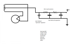
if there is anything i can ever do for you let me know. i just recieved a supply of 500 100ohm 1 watt resistors if you need a pile let me know, they are very accurate.they are russian manufacture (this is kind of a joke, i ordered them because they were so cheap)
i have a proper good quality protoboard designed specificaly for 9pin tubes, i bought it off of ebay.
this is the power supply. i measure 205 volts at B+. presently i only have 2 capacitors installed and not the optional one which i ordered with a similar value of 450 volts. i cant find one for 630v though 500v is available im just wondering if 450 isnt enough
i have to read your post several more times and then i will probably be able to reply more to it. im going to copy it all into my note book
i get 205volts to the plate 220k plate resistor
342volts of rectified unfiltered dc off of the secondary
thanks again
Attachments
Last edited:
the cathode voltages are .6v on average.
i have been studying your schematic and i it confuses me less now.
is the parallel triodes a really bad idea?
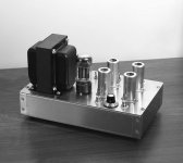
here is a picture of the chassis i have with the world voltage power transformer
i do get scratchy sounds when i turn the volume pot, i tought it was poor quality pot but there are other consderations as well it seems dc at the input of the preamp
thanks again
i have been studying your schematic and i it confuses me less now.
is the parallel triodes a really bad idea?
here is a picture of the chassis i have with the world voltage power transformer
i do get scratchy sounds when i turn the volume pot, i tought it was poor quality pot but there are other consderations as well it seems dc at the input of the preamp
thanks again
Attachments
Last edited:
Hello,
This is one of the best threads.
From the point of view, no one is totally useless you can always serve as a bad example, Steve’s’ circuit is a great project kit. Clearly it is operating at the knee of the plate curves. Starved as it is I am sure that it has ample single End Triode distortion to take the Digital edge off your MP3’s.
Plug it in and play it. Enjoy it. That first tube project is really cool.
Consider possible improvements over a few days. Cleaning up the grounding may help with the hum. The female RCA inputs and outputs look to be grounded to the chassis. There could be a lot of hum in that aluminum can. For $0.40 each you can use these http://apexjr.com/images/RCA2.jpg to isolate the signal ground from the can. Next I would rectify and place a smoothing capacitor on the heaters. (bridge rectifier + 10K uf to 20K uf electrolytic capacitor)
Dual Triode
All just for fun!
I think the thing that is bothering a lot of us here is that if this circuit was actually intended to be the way it was originally drawn, well, I think we share your consternation in that realization. That is why we have thought that maybe your original schematic was not right.
Arnulf's circuit is a good one and incorporates a lot of what I was talking about. The nice thing is you have the platform and you can make it work. Have fun and don't zap yourself!
Arnulf's circuit is a good one and incorporates a lot of what I was talking about. The nice thing is you have the platform and you can make it work. Have fun and don't zap yourself!
- Status
- Not open for further replies.
- Home
- Amplifiers
- Tubes / Valves
- too much gain