Hello,
Where theory meets practice there is a point where theory fails to explain the details. Plate curves and load lines are not straight lines; rp, mu and gm are not constants. Theory and math is a place to start, understanding what you know is the goal.
For this current project put on your eye and ear protection, plug it in, measure it, record the data, turn it up until it explodes, go to bed, read, dream about it, adjust your assumptions and repeat the process for the next 30 years.
BTW Keep the transformer.
DT
It is all just for fun!
thanks a lot man. that's awesome 😛
Sorry, I didn't have time yesterday to explain it better. First thing to do is understand Ohm's Law. You have 205 volts at one end of the 220k resistor and 13 volts at the other. That means a drop of 192 volts. OK, with this info and thanks to Ohm's law you can calculate the current passing through the 220k resistor; to avoid mistakes with decimals use the program. You want to know the current so fill out the resistor value and the amount of voltage drop: 220k and 192 volts = .872 mA. That is the current passing through your tube.
Next thing is to understand there are tubes designed to work with low currents but the 6n1p isn't one of them. There are other tubes designed to work with 12 volts at the plate but the 6n1p isn't one of them. WRONG circuit.
Next thing is to understand there are tubes designed to work with low currents but the 6n1p isn't one of them. There are other tubes designed to work with 12 volts at the plate but the 6n1p isn't one of them. WRONG circuit.
i was hoping you could walk me through it
Ohm's law is: I=V/R, where I is current in amps, V is volts, and R is resistance in Ohms. The expression can be rearranged to: V=I*R, and R=V/I.
Power in watts, is current times voltage, or: W=I*V. Since V=I*R, then power can also be expressed as: W=I*I*R. Likewise, since I=V/R, watts can be expressed as: W=(V/R)V, or (V*V)/R.
For power calculations, volts can be either DC volts or AC volts RMS. RMS means Root Mean Square. You don't have to worry about that meaning much, but you do have to remember the practical application. For instance, 100VDC is just that, 100V across a resistance. However 100V AC (RMS is assumed, unless otherwise indicated) generally assumes a sine wave that swings from 141V positive to 141V negative (100 times the square root of 2). For AC, the power varies instantaneously. But the average power over time, across a given resistance, is the same for 100VDC or 100vRMS AC.
The other thing to remember about for AC circuit calulations, is that a 1vRMS signal, for instance, means a swing from +1.4 to -1.4volts, or a point to point swing of 2.8V. In other words, a 1vRMS signal on the input grid, causes the total swing on the grid to span 2.8V.
If you don't understand this much, study until you do. Until this is understood, nothing else will make sense.
Sheldon
Sorry, I didn't have time yesterday to explain it better. First thing to do is understand Ohm's Law. You have 205 volts at one end of the 220k resistor and 13 volts at the other. That means a drop of 192 volts. OK, with this info and thanks to Ohm's law you can calculate the current passing through the 220k resistor; to avoid mistakes with decimals use the program. You want to know the current so fill out the resistor value and the amount of voltage drop: 220k and 192 volts = .872 mA. That is the current passing through your tube.
Next thing is to understand there are tubes designed to work with low currents but the 6n1p isn't one of them. There are other tubes designed to work with 12 volts at the plate but the 6n1p isn't one of them. WRONG circuit.
thanks for this explanation it really clarifies things
how much current should be running through this tube and what would you say the resistor value should be
Here's here you should know about plate curves but it's not that easy as understanding Ohm's law.
http://www.audioxpress.com/resource/audioclass/ga699ac.pdf
A minimum of 2-3 mA for linear operation, the 220k won't do, a lower plate resistor is necessary. Arnulf's schematic is OK.
http://www.audioxpress.com/resource/audioclass/ga699ac.pdf
A minimum of 2-3 mA for linear operation, the 220k won't do, a lower plate resistor is necessary. Arnulf's schematic is OK.
Here's here you should know about plate curves but it's not that easy as understanding Ohm's law.
http://www.audioxpress.com/resource/audioclass/ga699ac.pdf
A minimum of 2-3 mA for linear operation, the 220k won't do, a lower plate resistor is necessary. Arnulf's schematic is OK.
2-3 mA, thanks
and thanks for the link that is great!
Last edited:
I like this bit from the DualTriode but want you to remember that this sort of experimentation is for low energy circuits only. By low energy, I don't mean necessaritly low voltage.Hello,
Where theory meets practice there is a point where theory fails to explain the details. Plate curves and load lines are not straight lines; rp, mu and gm are not constants. Theory and math is a place to start, understanding what you know is the goal.
For this current project put on your eye and ear protection, plug it in, measure it, record the data, turn it up until it explodes, go to bed, read, dream about it, adjust your assumptions and repeat the process for the next 30 years.
BTW Keep the transformer.
DT
It is all just for fun!
Here's a term to lookup. Joule(s). It's a unit of measurement of raw energy provided by a circuit. In some power supplies; i.e. transmitters and very high power equipment like radar etc. this figure gets large. When you plug a circuit with a very high energy level into a dead short the resultant firworks make guys like TubeLab (George) and me get excited. Your pre-amp doesn't fall into this category but as your explorations continue you might start fooling with big power and things get interesting fast.
There's nothing like letting the smoke out of a few components first thing in the morning.
I built an amp for a guy in England and did everything right except change to the proper MOV spike protector. It made a very satisfying BANG! when I turned it on for test. Skeert me, and I ain't askeert o' nothin'.
Seems to me I mentioned something like that earlier.2-3 mA, thanks
and thanks for the link that is great!
Do you have any test equipment, like a sine wave generator and an oscilloscope? If not, and you find that doing this has some appeal, those are two bits of test equipment that you will find quite handy!! Along with your trust DVM of course.
Seems to me I mentioned something like that earlier.
Do you have any test equipment, like a sine wave generator and an oscilloscope? If not, and you find that doing this has some appeal, those are two bits of test equipment that you will find quite handy!! Along with your trust DVM of course.
did you mention that? sorry, i have a lot going through my mind not everything sinks in, too much lds in the 70s.
i have a usb oscilloscope. stupid i didnt buy a better one but i was impatient. it cant handle high voltages
Seems to me I mentioned something like that earlier.
Do you have any test equipment, like a sine wave generator and an oscilloscope? If not, and you find that doing this has some appeal, those are two bits of test equipment that you will find quite handy!! Along with your trust DVM of course.
i have two DMMs one is fluke i bought used from ebay but its ohm readings arent accurate i think it needs to be calibrated but that costs about 70 dollars.
i do find this to be an appealing endeavour. the whole thing about voltages and conductances, thermionic emission, transconductance, power dissipation etc is so amazing and that we can manipulate these forces and principles to create functioning components for our pleasure (and unfortunately for war too).
an electronic device is almost a living thing. the human body is an electronic device on a much more sophisticated level plus there is something in the mind which makes it truly alive. a stereo amplifier has its parallels for sure. like i said too much lds in the 70s
it cant handle high voltages
You may use an attenuator made of couple resistors.
an electronic device is almost a living thing.
Everything is a living thing, including the Universe. Dead matter can't create a live one, simply because in order to start living dead matter have to be organized into the thing that is capable to maintain a dynamic equilibrium. It is impossible to gain such properties step by step, because without the single one it won't be living (i.e. in dynamic equilibrium), due to the main Law of Thermodynamics.
Last edited:
You may use an attenuator made of couple resistors.
Everything is a living thing, including the Universe. Dead matter can't create a live one, simply because in order to start living dead matter have to be organized into the thing that is capable to maintain a dynamic equilibrium. It is impossible to gain such properties step by step, because without the single one it won't be living (i.e. in dynamic equilibrium), due to the main Law of Thermodynamics.
absolutely true. wich came first the chicken or the egg? the chicken came first, complete and perfect with its ability to lay eggs. too bad preamps dont come complete and perfect with the ability to amplify my favourite CDs
absolutely true. wich came first the chicken or the egg? the chicken came first, complete and perfect with its ability to lay eggs. too bad preamps dont come complete and perfect with the ability to amplify my favourite CDs
You know, according to anthropologists and archaeologists an ax was made in many parts of the world almost simultaneously, being built from different materials, but of the same shape. No communication devices or transportation equipment is known to exist then. That means, an ax was created by The Universe, but made by men.
The same about preamps. Even if they were created by Universe, a man is always needed to finish the project.
So, it is your duty now to figure out how to create a voltage divider in order to use your oscilloscope for tube equipment. 😉
An Axe like the perfect amp must preexist as an idea, always providing you believe in the notion of time of course, now where's my copy of Zen and the Art of Motorcycle Maintenance? 😉
Who's going to write Zen and the art of Tubes?
Wavebourn- can't you use a 100 x probe to work with the higher voltages on a Digital oscilloscope? They are only $35 buck or so. Correct me if I am wrong.
Who's going to write Zen and the art of Tubes?
It will be called mentally controlled non-locality and coherence in audio cables. 😀
Wavebourn- can't you use a 100 x probe to work with the higher voltages on a Digital oscilloscope? They are only $35 buck or so. Correct me if I am wrong.
Yes, if it was made for the same input impedance.
That's a nice Schottky diode. I gotta write that number down somewhere.
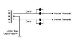
so i tried this arrangement with these diodes and the voltage drops down to 5.5v so then i though i would try only one pair of diodes on one leg and it started to smoke. i had a good 6v though. can anyone explain why it started smoking?
Attachments
Last edited:
so i tried this arrangement with these diodes and the voltage drops down to 5.5v so then i though i would try only one pair of diodes on one leg and it started to smoke. i had a good 6v though. can anyone explain why it started smoking?
What kind of diodes are they? Are you saying the diode started to smoke??
1n5822. the diode became so hot it melted the solder and the electrical tape started smoulderingWhat kind of diodes are they? Are you saying the diode started to smoke??
my sony sacd player arrived today. what a great sound!!
I'd be looking for shorts or a bad component. The diode is rated at 3Amps and I don't think your filament circuit has that in it!
- Status
- Not open for further replies.
- Home
- Amplifiers
- Tubes / Valves
- too much gain