Thanks Tony! I need to apologize for bothering all you with my idiosyncratic way to understand electronics. I'll be waiting for your project. Please save some space so that you could do a with/without CCS test. It would be very interesting!
no need to apologize, the only stupid questions are those that aren't asked...
i knew you would say "space" and when i am done with this amp, you will see that there will be little space left...
No doubt, even if the ear is the final judge, it cannot replace test equipment. One with a full pro bench where would seek for the difference a CCS makes?Unfortunately without some sophisticated test equipment that comparison will be subjective at best and wont clarify much at all.
Shoog
Sorry, guys (I do that very seldom: say "sorry"), but I'd state the very opposite: "the equipment can't ever replace my ear". It's not that mine is "golden", but quite realistically adjusted to what people consider be a "good sounding amp".
So many times I couldn't bare listening to the "amp" stated having 0.00000000001% THD, go figure.
Practically, yeah, if "the equipment" says the THD is over 3% you just do not bother, most likely it's a true low-quality one. But if less, it depends on the design, and a lot on the perception.
So many times I couldn't bare listening to the "amp" stated having 0.00000000001% THD, go figure.
Practically, yeah, if "the equipment" says the THD is over 3% you just do not bother, most likely it's a true low-quality one. But if less, it depends on the design, and a lot on the perception.
While waiting for Tony's progress, I would like to ask if there is a full circuit description somewhere. Actually, the audio circuit has been explained in the begining of the thread and this covers me but the power supply is much different from what I'm used to see, especially the ground scheme.
i do not see anything different at all in the psu, it is just an implementation of the Tabor circuit...
the amp will be grounded to chassis at just one point and that point would be where the signal is lowest, at the input stage...
there are two ac loops, one at the output tube stage and another at the input ltp stage,
in terms of dc, two power supplies are stacked one on top of another, that
is clear to see from the scheme...
Yes, all this is understood. What I don't understand is the function of the lowest 20mA CCS and the heaters DC elevation attached to only one transformer's CT going to a and b. Also the OPT secondary is connected to ground via the 4 ohm tap. Some good reason for this and I thought it might be interesting to know. Finaly, input XLR's pin 1 is going to a ground lifter. I would expect pin 1 directly to chassis and the ground lifter from circuit ground to chassis. OTOH, in balanced topology a ground lifter might not needed at all, so I was wondering if Gary Pimm was doing something else here.
just think of it this way, a CCS by definition will change its terminal voltage to maintain current, what would happen if a simple resistor was used instead?
The way i have my power supply is slightly different to the original. The front end is loaded with a negative supply via the input transformer CT and a shared CCS on the cathodes. This allows me to set the plate voltage of the input stage at about zero volts DC. The screens are referenced to earth.
The output stage has a conventional supply and the separate CCS on their cathodes both sets the bias of the Output stage and adjusts for variations in the input stage plate DC potential. This is a slight bit wasteful as I like to give them an extra 10volts or so to play with for this adjustment.
I think that is somewhat simpler than the original design.
Shoog
I don't know if I can see it clear. In the original design, the 20mA CCS is used to adjust the relative DC levels of the circuit?
in the rev.3 scheme there is a 20mA ccs supplying the front end psu VR regs that supplies G2 of the input LTP...
I see. I was only looking at R3 with regard to the stabilizers...
that too, if you look at the 500 ohm resistor and the CCS they are in series with the VR tubes....
if you know the voltage drop across the 20mA ccs, you can actually replace it with a fixed resistor instead....
the 500 ohm resistor isolates the VR tubes from the big filter caps, without the resistor, you can only use about 0.1ufd capacitor there...
That's a rather short tail! If I understand correctly Tabor rev.3 schem as posted at the begining of the thread, the psu provides a headroom of some 70V to the tail CCS of the 1624. Meaning 60V added to B+ if cathode resistors used. Would this matter wrt the direct coupled design?
sorry i made a mistake in my earlier calculations...as with any CCS it is the current that is important, not the voltage...
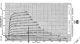
Even though 1624's datasheet suggested using 1619's curves, I do not think the two tubes are interchangable, look at the no-sig. current shown in the 1624 datasheet, it is clear that the bias condition is quite different from what is shown by the 1619's curves... It would be great if you can trace a few 1624's to find out what's going on...

yes, Jerry i am flip-flopping now.....this is a direct coupled amp, i will post results results after i powered it up...
i think i now realized that the choice of CCS was indeed the best choice, no need to worry about resistor values....
i think i now realized that the choice of CCS was indeed the best choice, no need to worry about resistor values....
This amplifier is difficult to repeat to radio amateurs. In his winding, he used a wire in Kel-F ( TECAFLON,Teflon-3) insulation and rather thick insulation. I've never seen such on sale. Although I was told at the plant that they can make a special double-sealed enamel wire plus Teflon-4 insulation by special order. Apparently, Bereskin in 1958 had a rich and ambitious customer.I but interesting post you have, your mention of Bereskin rang beautiful bells in my head...
been looking at Bereskins' high power tube design using the 4-400 tubes...
i am wondering who else aside from him has done the traffo he mentioned in that article...?
Last edited:
- Status
- Not open for further replies.
- Home
- Amplifiers
- Tubes / Valves
- Tony's TABOR amp clone wannabe build log.....