Tony,
You can get the details on several versions of Gary Pimm's CCS by calling up his website on Archive.org via the Wayback machine: www.pimmlabs.com. Two versions of the Tabor amp, too.
rus
thanks...i have not used the wayback machine before, will take time to learn it..
Its pretty straightforward; go to www.archive.org and at the top of the page where it says Wayback Machine enter the URL for Gary's website: www.pimmlabs.com then hit return. I comes back with a calendar with dates that it sampled the site. I picked the first date in January 2013 and got access to that version of the website on that date. Very useful for finding things that have disappeared from the net.
rus
rus
Positive FB got it a bit over simplified I think. The input stage's output Z is of course its plate resistance in || with the load resistor. To book-end the situation keeping the GP circuit in the output stage intact, we take an active device with gm of 2A/V, and a plate resistance of a MOhm. Given the 68k( IIRC ) plate load resistors currently attached to 6AU6's the output Z of the stage will be just a hair less than 68kOhm. It isn't this output Z that makes it work though, it is the plate resistance of the 6AU6( or my 2A/V substitute).
Take the E-Linear circuit, with B+ fed to the driver plates from a tap along the plate winding. The plate resistance of the amplifying device sets how much FB is delivered. Make it a 12B4 and FB will be substantially different than if an EL84 was attached in its place. Pete Millett wrote up this circuit for AudioXpress in SE with a D3A, while I was working with Emotive Audio and developing a PP circuit( Fred already had fine SE offerings...LOL ).
cheers,
Douglas
the OPT i used did not have ultralinear taps unfortunately....
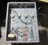
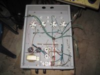
i will proceed building and testing the psu using dummy loads and see
if the psu comes up to speed...
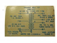
84 watts total plates,300v plate/70 mA cathodes and about 2x 16 watts on the CCS.
will check what adjustments to the psu needed to be done...
yes Jerry, and i am mulling separate CCS for each cathodes of the 1624....
Tony - I don't understand how separate CCSes are going to work. They will not allow current swings through load halves.
Also, if I recall Gary's pretty detailed description of design progress with similar (and earlier) 47 pentode amplifier, bias voltage stability of DC-coupled design was a problem. Manual bias setting required adjustment every few minutes to maintain output stage balance. In the final version, Gary came up with bias servo, but that has problems too. Since I've read Gary's blog, I had strong temptation to build this kind of amplifier, but got frustrated by this unsolved problem of maintaining stable bias.
as i said i have not made up my mind on that..
i am not even sure what the final topology will be, but thanks for your inputs..
for now i have a platform that i can use....
i am not even sure what the final topology will be, but thanks for your inputs..
for now i have a platform that i can use....
Will be following your progress with much interest.
I also got a stash of 1624 tubes a while ago, and since then was pondering what to do with them. Tabor is probably the best of what one can come up with.
They are neither good as triodes, nor as Class A or AB1 pentodes. Their forte is AB2. They are highly linear at positive control grid voltages.
Now that I got a nice interstage transformer, I will try 3 stage all-differential, transformer-coupled AB2 with all directly heated tubes. Triode 1P24B voltage stage, triode 46 (or 47, which is 46 with suppressor grid), and 1624 AB2 power stage.
Attachments
Not so difficult and huge with 0,25 mm magnet wire which can have the current.
To reach 500 ohm It will have large L which is good.
To reach 500 ohm It will have large L which is good.
Not so difficult and huge with 0,25 mm magnet wire which can have the current.
To reach 500 ohm It will have large L which is good.
yes, that would be #30 awg wire, and to get 500 ohms,
i will need around 4800 feet of wire and weighs in at around 1.5 pounds
copper density is 0.33 pounds per cubic inch so volume needs to
be 4.5 cu inches....
looking at cores that i have, looks like an EI 1in. center leg stacked to 1 inch can do...
winding window of about 0.75 sq inches, mean length per turn of say 5 inches,
turns will be 2000 turns.....
there will be plenty of space, perhaps a 7/8 inch core can be used...
the reason for putting a choke in the output stage is to bias the output tubes to take it to the correct operating point...
several ways to get there..
several ways to get there..
Yes, it can be done either by placing choke on top or at the bottom. If choke drops a lot of voltage, you have to watch for heat dissipation. Even large choke with copper dissipation of 10 W will run hot.
Also, because copper resistance strongly increases with temperature, a long warm-up time will be needed for bias to stabilize.
Also, because copper resistance strongly increases with temperature, a long warm-up time will be needed for bias to stabilize.
Last edited:
yes, the coils will be dissipating 10 watts...
i am not using a cathode choke with this build...
i am not using a cathode choke with this build...
Maybe you speak for US made new production chokes?
I know of several European brands, and quite likely a few Asian brands as well, who make layer insulated chokes. A good choke is not just randomly winding an x amount of turns on a bobbin.
Of course one blanket statement does not cover products from hundreds of manufacturers during the period of over 60 years.
It is very easy to see whether or not a choke has extra insulation between winding layers.
One of the important things that defines choke quality is low shunt capacitance. This is achieved by winding sectioning and extra insulation between layers.
That's right. Choke's impedance increases with frequency until shunt capacitance comes into play and impedance starts decreasing. Within its frequency range, choke acts as long tail or CCS.
yes, but at what frequency? in this case what frequency is that.....?
while we can parade theories here, i need actual numbers really appreciate....
May be I read the schematic wrong (it's very poorly drawn)... but there appears to be two separate filament windings for each of the 252's, i.e., no common choke.
the choke on top is to ensure lowest possible psu ripple....
the choke has an associated filter cap that effectively renders it
at ac ground, well very low frequency close to 0 hz, well outside of the audio band...
The problem is that choke manufacturers don't publish shunt capacitance of their products, and values could be all over the place from 50 to 500 pF for a 20 H choke. Capacitance can be measured, but it is somewhat complicated. I wouldn't be too much concerned at this point. Proceed with your build, and then measure frequency response of your amplifier. If there is unacceptable HF roll-off, you might need another choke, but chances are that you will be OK with what you have.
No, no, no, no, no.
If it was smoothing choke, there would be a capacitor from output transformer CT to ground, but there is no such capacitor. I am talking about lead 2 of L2 in the schematic. L2 is common choke that acts similar to CCS.
in that case, i am not interested...
- Status
- Not open for further replies.
- Home
- Amplifiers
- Tubes / Valves
- Tony's TABOR amp clone wannabe build log.....