Wow, those are monster C cores! What power capability would your estimate at 50Hz grids?
Best regards!
this was from an isolation traffo rated for 1000watts/50 hz...300 watts at 30 hz is a reasonable expectation imho...
360VA if you can squeeze in the same amount of copper and can liv with the distortion at maxed out induction.
I use 0.5T at 50Hz for lowest distortion (distortion increases at higher induction, starting from 0.4T, inductance reaches a max somewhere between 0.8 and 1.2T), this would give at most 80W output but it all depends on what you need or want want. In the old days 0.4-0.6T at 40Hz (allowing maxed out inductance at 20Hz) was considered best for minimum distortion with 3%Si Goss (McIntosh squeezed out a bit more, 75W with only 4kg of iron, but that is because the high amount of fb allowed for a bit higher transformer distortion)
I use 0.5T at 50Hz for lowest distortion (distortion increases at higher induction, starting from 0.4T, inductance reaches a max somewhere between 0.8 and 1.2T), this would give at most 80W output but it all depends on what you need or want want. In the old days 0.4-0.6T at 40Hz (allowing maxed out inductance at 20Hz) was considered best for minimum distortion with 3%Si Goss (McIntosh squeezed out a bit more, 75W with only 4kg of iron, but that is because the high amount of fb allowed for a bit higher transformer distortion)
Last edited:
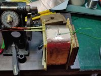
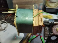
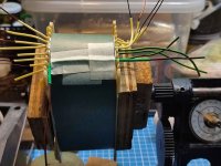
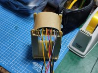
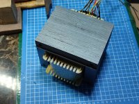
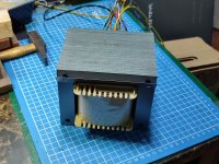
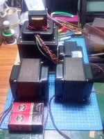
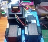
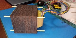
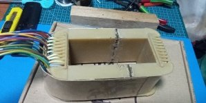
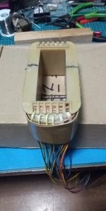
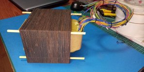
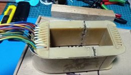
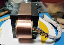
this is a power traffo using a 2inch center leg stacked to 3 1/4 inch DEECO silicon steel (noss) irons..
specs are as follows:
primary: 220 volts 60hz.
secondary1: 250volts at 2amps.
secondary2: 100volts at 0.5amps
secondary3: 12.6volts at 10 amps
secondary5&6: 6.3 volts at 3 amps
http://s5.photobucket.com/user/leoman53/media/tony trAFFOs/110711p- 036_zpsh8kt3qpt.jpg.html
http://s5.photobucket.com/user/leoman53/media/tony trAFFOs/110711p- 037_zpse0vzghcy.jpg.html
http://s5.photobucket.com/user/leoman53/media/tony trAFFOs/110629a-016_zpscljmyrko.jpg.html
http://s5.photobucket.com/user/leoman53/media/tony trAFFOs/110711p- 040_zpsgn2c8can.jpg.html
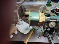
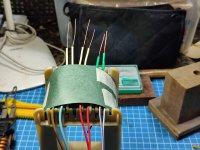
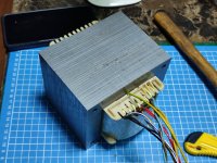
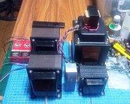
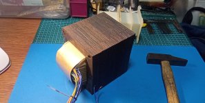
completed, there are 3 chokes sitting on top, 1/2inch, 5/8 inch, aqnd 3/4 inch.
http://s5.photobucket.com/user/leoman53/media/tony trAFFOs/110711p- 041_zpsso6g7jgm.jpg.html
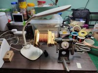
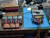
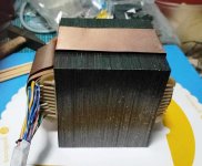
testing prior to dipping in polyuretahne varnish
line voltage:
magnetizing current:
unloaded core apparent power:
actual unloaded power in watts:
power factor:
Dear Tony,
I have a tube preamp thet wants 120V and 12V power supply fom 230V AC EU mains power.
Would it be possible for you to make me a transformer with dual 120V and 12V outputs like the one here? Please quote in PM.
Greetings,
Mario G Rouwenhorst
Netherlands
Dear Tony,
I have a tube preamp thet wants 120V and 12V power supply fom 230V AC EU mains power.
Would it be possible for you to make me a transformer with dual 120V and 12V outputs like the one here? Please quote in PM.
Greetings,
Mario G Rouwenhorst
Netherlands
Mario, very sorry for the late reply, i design and build traffos for my own projects, but i am not a commercial entitity, sorry i do not sell transformers.....
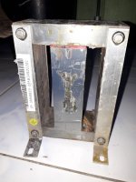
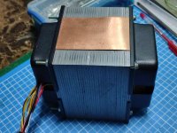
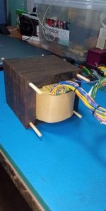
found a core i was looking for a long time....
Attachments

Last edited:
Good day sir! I just want to ask if you use 500cma both in power trafo (even the heater 6.3v tap) and output trafo?these are tables i made to assist you in designing trafos....ampacity can be anywhere from 700 circular mils per ampere to 300 cma, i start design using the 500 cma column..
Thank you so much. Hope you respond. 🙏
500 cm is just about right, if space in the bobbins or winding window allow 700 cm then go ahead and use it..
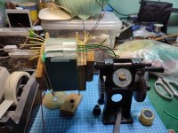
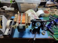
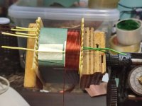
latest traffo build for an amplifier build....1 3/4 inch center leg stacked to 4 inches, using 0.35mm H18 laminates
Attachments
-
 IMG_20230113_090339.jpg377.4 KB · Views: 253
 -
 IMG_20230113_085914.jpg481.9 KB · Views: 246
 -
 IMG_20230113_085908.jpg398.3 KB · Views: 238
 -
 IMG_20230112_173518.jpg431.9 KB · Views: 236
 -
 IMG_20230112_172457.jpg437.6 KB · Views: 238
 -
 IMG_20230112_171945.jpg428.2 KB · Views: 226
 -
 IMG_20230112_171940.jpg330.4 KB · Views: 222
 -
 IMG_20230112_162001.jpg384.4 KB · Views: 221
 -
 IMG_20230113_090343.jpg477 KB · Views: 229
 -
 IMG_20230113_104454.jpg395.2 KB · Views: 222
 -
 IMG_20230113_105243.jpg399 KB · Views: 222
 -
 IMG_20230113_111905.jpg502.6 KB · Views: 226
 -
 IMG_20230113_151335.jpg494.7 KB · Views: 211
 -
 IMG_20230113_151340.jpg508.7 KB · Views: 209
 -
 IMG_20230113_155813.jpg554.2 KB · Views: 213
 -
 IMG_20230114_135359.jpg620.4 KB · Views: 225
 -
 IMG_20230119_132216.jpg503.8 KB · Views: 251

Impressive, as ever  . I wish I'd have a winding machine and all the materials.
But I wonder why you're stacking the laminations this high instead of chosing bigger lams with a wider center leg to get a more square center cross section. The higher the quotient of height and width, the higher the turns length, which turns into higher DC resistances, and the higher the inter and intra winding capacitances.
Best regards!
. I wish I'd have a winding machine and all the materials.But I wonder why you're stacking the laminations this high instead of chosing bigger lams with a wider center leg to get a more square center cross section. The higher the quotient of height and width, the higher the turns length, which turns into higher DC resistances, and the higher the inter and intra winding capacitances.
Best regards!
Hi Kay Pirinha,
i have about 30+ kilograms. of these material to use that is why the choice...there is more than enough core material to supply power so that dcr's not a concern....
i have about 30+ kilograms. of these material to use that is why the choice...there is more than enough core material to supply power so that dcr's not a concern....
Last edited:
https://www.diyaudio.com/community/threads/tonys-latest-traffo-diy-build.191730/page-53#post-7317549
Wow! 53 pages of 12 yrs of trafo builds...
I've only done 1- have new appreciation for the level of patience and dedication 53 pages takes; impressive!
Jim
Wow! 53 pages of 12 yrs of trafo builds...
I've only done 1- have new appreciation for the level of patience and dedication 53 pages takes; impressive!
Jim
thanks, i am a hobbyist, not a commercial winder..Wow! 53 pages of 12 yrs of trafo builds...
I've only done 1- have new appreciation for the level of patience and dedication 53 pages takes; impressive!
Jim
I myself have big admiration for Sir Tony's expertise.
He is a well-respected Audio enthusiast in PH, approachable and a guru who unselfishly share his experiences.
He has helped me a lot and encourage fellow audio enthusiast.
He is a well-respected Audio enthusiast in PH, approachable and a guru who unselfishly share his experiences.
He has helped me a lot and encourage fellow audio enthusiast.
Tony, it is impressive!
I want to start winding a small transformer, could you give me advice?
Regards
Steven
OK, I just read the 53 pages to see if you published someting similar 🙂
I want to start winding a small transformer, could you give me advice?
Regards
Steven
OK, I just read the 53 pages to see if you published someting similar 🙂
i made a power transformer for kt88/kt90/kt120/kt150/kt170. HT taps are selectable for up to 600vdc
bobbin welded to make a 114100 traffo..
bobbin welded to make a 114100 traffo..
Attachments
-
 1000001513.jpg59.9 KB · Views: 154
 -
 1000001512.jpg81.8 KB · Views: 154
 -
 1000001510.jpg81.6 KB · Views: 161
 -
 1000001508.jpg74.5 KB · Views: 166
 -
 1000001506.jpg69.7 KB · Views: 157
 -
 1000001505.jpg64.9 KB · Views: 161
 -
 139163d3-b804-44e3-b35c-67b8fb677eddphoto.jpeg460.6 KB · Views: 147
 -
 235ec275-6f5a-49eb-a88a-c03d31bb5143photo.jpeg512.7 KB · Views: 156
 -
 5e0f8d7f-18f1-4f13-8473-842cd7875ee1photo.jpeg402.8 KB · Views: 154
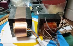
more pics, a side by side comparison with the original PA-060 ST-70 power traffo...
Attachments

- Home
- Amplifiers
- Power Supplies
- Tony's latest traffo DIY build