Hi Diyrayk,
I fully agree, exactly the scrubbing is causing FM modulation giving these sidebands.
Maybe the term IM that I used was the misleading.
Hans
I fully agree, exactly the scrubbing is causing FM modulation giving these sidebands.
Maybe the term IM that I used was the misleading.
Hans
Off topic for a split second if I may; Hans, any relation to the Porsche race car driver from the 70's?
You mean this ?
Hans
Attachments
Yup interesting. Theoretical FM modulation from srcubbing should have a series of sidebands at integer multiples of the modulating frequency ie 10Hz 20Hz 30Hz....and looks like there's part of that series.
But I think one should anticipate the same FM on any vector, vertical. or lateral. This is because stylus is only free to scrub along along the line of the groove. Even if there wont be much test tone level on L-R vector (vertical) it must still show the same FM....?
LD
But I think one should anticipate the same FM on any vector, vertical. or lateral. This is because stylus is only free to scrub along along the line of the groove. Even if there wont be much test tone level on L-R vector (vertical) it must still show the same FM....?
LD
Hi Diyrayk,
I fully agree, exactly the scrubbing is causing FM modulation giving these sidebands.
Maybe the term IM that I used was the misleading.
Hans
Hans,
I was trying to lead you down the road of further exploring inherent differences in pivoted offset arms vs linear trackers. To do that, horizontal and vertical behavior needs to be analyzed separately.
Ray K
Ray: Can't the files just be post processed to mid and side?
umm, hadn't thought of that. Maybe what I'm asking for is easier than I envisioned. I just don't have the computer/software setup to pull it off myself.
Ray K
The problem I'm struggling with is how to map -42dB sideband amplitude onto an index for how deep the FM modulation is?
If it were as simple as a ratio, which i doubt, -40dB would mean pitch variation of 1%. that would not be good ?!
Yes, although FM at low modulation levels starts out with substantially only 1 pair of sidebands, at which point it looks like AM.Yup interesting. Theoretical FM modulation from srcubbing should have a series of sidebands at integer multiples of the modulating frequency ie 10Hz 20Hz 30Hz....and looks like there's part of that series. LD
But I think one should anticipate the same FM on any vector, vertical. or lateral. This is because stylus is only free to scrub along along the line of the groove. Even if there wont be much test tone level on L-R vector (vertical) it must still show the same FM....? LD
Um, good point about not much test tone level on the vertical, oops. But, the FM is not the same, vertical or lateral. The lateral FM is highly influenced by the presence or absense of offset angle and overhang in the geometry.
Ray K
The problem I'm struggling with is how to map -42dB sideband amplitude onto an index for how deep the FM modulation is?
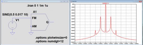
When I've done it right, the FM modulation index is +/- the frequency deviation divided by the modulation frequency.
Modulator was set as Space=995 and Mark=1005.
In this case with ca -42dB for the first sideband:
m=0.017*5Hz/10Hz=0.0085
Hans
Attachments
Thx Hans. Hmmm if I understand that's pitch variation of c 1% ?? So not sure how to reconcile with IIRC the threshold of audible perception c 0.1% and past polar plots from several sources that show results around that threshold?
Well this is a learning experience for me and you'll have to talk me through this one Hans pls. I dont get your 5Hz/1kHz ratio calculation, plus not familiar with LTspice MODULATOR component...though it looks like a great new toy...
Also 0.01% outcome is about a decade too small to be realistic...
LD
Also 0.01% outcome is about a decade too small to be realistic...
LD
LD,
The modulator was set with Space=995 and Mark=1005.
The FM input was driven by a 10Hz signal with an offset of 0,5 volt.
When giving the input signal an amplitude of +/- 0,5V, it goes from zero to 1Volt and the modulator goes from 995Hz to 1005Hz.
Pitch variation in that case is 5Hz/1Khz is 0.5%.
However I needed only +/-0,017V instead of +/-0.5V as you can see in the simulation to get the first sideband at -42dB.
(0,017V/0,5V)*0,5%= 0,017%, which is safely below 0.1%.
Hans
Thanks Hans, yup all looks good I get that.
A swift check on the famous B&K paper shows 1st sidebands typ -20dB to -30dB or so though the graphs are noisy to read so really looks like you have in those conditions an unusually stable rig!
I think it might be good to do a swift table or graph that maps 1st sideband level onto % pitch variation, then the method would be quantative something that even B&K didnt manage?
LD
https://www.theanalogdept.com/images/spp6_pics/TT_Design/MechanicalResonances.pdf
Here's that B&K paper link.
Here's that B&K paper link.
All well and good, it looks like we’ve reached cruising altitude and we’re stabilized under steady state conditions. Now, what happens when we kick this airplane with turbulence in the form of a dynamic stylus friction transient caused by a sudden modulation change like a loud cymbal crash or a Telarc canon shot? Whenever the arm pivot is not in line with the axis of the cantilever, a dynamic stylus friction transient will generate a force that ultimately resolves itself into deflecting the cantilever, which results in stylus scrubbing and a transient blip of FMD. It could trigger a bout of mass/compliance resonance and the transient FMD could linger or decay depending on system damping. The nature of the FMD will vary depending whether the scrubbing is from vertical deflection or horizontal deflection, which depends on arm geometry.
I posit that the transient FMD behavior of an arm/cartridge system is more telling, and likely worse than, the steady state FMD behavior that we are measuring and talking about here. The trick is how to measure and quantify the transient FMD and then to establish threshold level(s) of what amount(s) is/are audible.
Ray K
I think it might be good to do a swift table or graph that maps 1st sideband level onto % pitch variation, then the method would be quantative something that even B&K didnt manage?
LD
LD, here you are.
Hans
.
Attachments
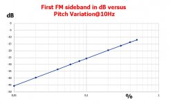
Thx Hans. I'm not sure yet this can quite be right...understand it obtains from the spice component model but....shall check out the maths and theory, plus I think if yer look at it from energy perspective all modulation should end up in the sidebands? And for small modulations that means 1st and maybe 2nd mostly, ie mostly a simple ratio...so maybe its time for me to understand it properly (groan :-; )
LD
LD
LD, I modulate an FM modulator with a certain percentage. I'm not looking at anything else but the position of the first sideband in the FFT spectrum.
So this is real level in dB, no distribution of power over the other sidebands.
Hans
So this is real level in dB, no distribution of power over the other sidebands.
Hans
- Home
- Source & Line
- Analogue Source
- Tonearm/Cartridge/Compliance: Compatability