The EPA100 test was with two cartridges a Stanton 881s compliance 30 x 10-6 dyne at 10Hz and Technics EPC205 12 x 10-6 @ 100Hz. The Stanton in theory should not be a good match for this arm.
Here is a thread I created to document the EPA, the first tests were done with the EPC205 all others were the 881s.
Technics EPA100 modifications
Thanks great work!
The aluminium arrived today for the bearing housing (we are locked down ATM) Hopefully I'll have a working prototype in a week. This is going to be a 4 point arm in a gimbal arrangement, NO bearings. I have to grind and polish the pins, so there is a lot of work.
Re: ball races agree they are non ideal for tone arms.
With opposite point contact bearings I worry about thermal expansion loosening, pin point wears out quickly and may be damage prone. What's the 'best' contact surface material / geometry? And acoustic impedance diode / mirror effects? After all that's why we put spikes under speaker cabinets etc.!
So for the original run of 'Delta Inertia' spring arms I used off the shelf steel bearing pins (ground and polished hardened forgotten exact spec but mirror finish and tarnish resistant) housed in 'Oilite' (sintered brass to give slightly porous structure to hold medium viscous oil) bushes that I precision reamed to fit the pins. Very rigid with surprisingly low friction both due to oil film despite several mm2 of surface area.
The point of building this arm is to build a no-compromise tonearm with materials I have available.
I have 4 x sapphire Vee jewels for the pivot cups. These are designed to accept carbide pins, but I'm using tool steel ground at 55deg and polished to 1micron.
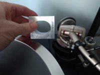
I completed the horizontal bearing housing today, pictured next to the Technics arm. This will be a very large arm. Built for rigidity.
I have 4 x sapphire Vee jewels for the pivot cups. These are designed to accept carbide pins, but I'm using tool steel ground at 55deg and polished to 1micron.
I completed the horizontal bearing housing today, pictured next to the Technics arm. This will be a very large arm. Built for rigidity.
Attachments

Since the arm integrates the energy of the stylus, dissipating this energy becomes an issue since it excites resonances in the arm. One forum member reported improvements using a sorbothane counter-weight. There are also sand filled arms.
There is always a lot of focus on precision engineering but little on dealing with the shock wave that transits solids. The stiffer and denser the solid, the more efficiently the shock wave travels. If there was more effort to deal with that energy, less would be available to provoke vibration in bearings and elsewhere.
Magnetic levitation does not really address this issue and may make it worse, confining more energy to the wand.
You are make an assumption I have not addressed tonearm energy. The most I mportant thing is the amount of energy reflected back to the cartridge.
This arm wand has variable wall thickness and taper to reduce refected energy. The removable headshell is made from the same section of aluminium and grain orientation as the wand.
It's made from 6061 T6. The plan is to make another from AZ31B magnesium.
This arm wand has variable wall thickness and taper to reduce refected energy. The removable headshell is made from the same section of aluminium and grain orientation as the wand.
It's made from 6061 T6. The plan is to make another from AZ31B magnesium.
Magnetic levitation does not really address this issue and may make it worse, confining more energy to the wand.
'Mag-lev' geometry has gimbal bearings for vibrational energy to pass, same as most standard counterweighted arms do, so energy is not confined to the wand.
Indeed, mechanical vibrational energy routinely crosses over gaps in magnetic fields, that's how electromechanical devices such as motors work.
This 2003 forum thread explains how. Its about the Schroeder tone arm, that suspends the arm wand & counterweight on a wire tensioned by two attracting permanent magnets (i.e. no gimbal bearings):
“The magnetic field creates forces that act to damp the components of any vibrations that are perpendicular to the field. It does this by inducing currents, in the magnetic material - not the air, which are then converted to heat in that material (unless they are drained in an electric circuit of some sort). So, there is an energy coupling, but it's independent of the air.”
DIY Schroeder Tonearm???
This means 'Mag-Lev' geometry is even better at dissipating energy out of the arm wand than relying only on gimbal bearings or magnet gaps alone.
My point was about dealing with the arm energy before it reflects or transits. The sand filled arm does this, though that approach is not elegant.
You can tell if the arm is damped by holding one end and letting the free end drop on to a hard surface like dense wood. If it makes a 'dink' sound, it is not damped. The sound changes as damping is added.
You can tell if the arm is damped by holding one end and letting the free end drop on to a hard surface like dense wood. If it makes a 'dink' sound, it is not damped. The sound changes as damping is added.
Last edited:
Acoustic impedance paths
(Note: Schroeder arm does not directly achieve this as it forfeits the energy path offered by gimbal bearings and instead only uses a magnetically tensioned flexible wire to partially restrict some of the 6 possible degrees of freedom and act as magnetically coupled low acoustic impedance path for arm energy into the turntable mass).
There are two sides in an electro mechanical transducer. The moving side. And the stationary side.
If the mass of each side of such a transducer is the same, then both sides will move the same distance / acceleration / velocity in reaction to grove modulations, and no signal will be generated.
This implies one side should have much more mass than the other, so we can measure the differences in relative distance / acceleration / velocity that groove modulations cause between these two masses.
If instead of sinking arm energy into the turntable, we dump it locally in the much lower arm mass, some groove energy will be locally turned to heat in that mass, and due to conservation of energy this must by definition mean its acoustic impedance is higher (i.e. absorbing) than without heating.
This means damping causes the cartridge body & arm wand mass (the heavy side of our electro mechanical transducer) to move more (its softer that's how it heats up) than if the arm wand were instead stiff and transmitted its energy across the bearings into the orders of magnitude larger mass of the turntable, where the same quantity of energy would cause a lower temperature rise for the same energy inputs. In turn causing lower mechanical disturbance i.e. better signal dynamic range.
My point was to sink arm energy i.e. "a 'dink' sound" into the turntable before it reflects or needs damping. Rigid large surface area 2 degrees of freedom gimbal bearings and Mag-Lev geometry provide two low acoustic impedance transit paths for arm energy into the turntable mass.My point was about dealing with the arm energy before it reflects or transits. The sand filled arm does this, though that approach is not elegant ... a 'dink' sound is not damped ...
(Note: Schroeder arm does not directly achieve this as it forfeits the energy path offered by gimbal bearings and instead only uses a magnetically tensioned flexible wire to partially restrict some of the 6 possible degrees of freedom and act as magnetically coupled low acoustic impedance path for arm energy into the turntable mass).
There are two sides in an electro mechanical transducer. The moving side. And the stationary side.
If the mass of each side of such a transducer is the same, then both sides will move the same distance / acceleration / velocity in reaction to grove modulations, and no signal will be generated.
This implies one side should have much more mass than the other, so we can measure the differences in relative distance / acceleration / velocity that groove modulations cause between these two masses.
If instead of sinking arm energy into the turntable, we dump it locally in the much lower arm mass, some groove energy will be locally turned to heat in that mass, and due to conservation of energy this must by definition mean its acoustic impedance is higher (i.e. absorbing) than without heating.
This means damping causes the cartridge body & arm wand mass (the heavy side of our electro mechanical transducer) to move more (its softer that's how it heats up) than if the arm wand were instead stiff and transmitted its energy across the bearings into the orders of magnitude larger mass of the turntable, where the same quantity of energy would cause a lower temperature rise for the same energy inputs. In turn causing lower mechanical disturbance i.e. better signal dynamic range.
The material of the arm is unchanged from what ever it happens to be. If the arm wand has a sound, then this represents spurious deflection. Adding damping increases the overall mass.
A tapered arm with no damping will not perform any better than a straight arm with damping in my view. SME 3009 uses balsa wood but the implementation is poor because the wood has a square cross section giving minimal contact with the round cross section. Sinking energy just leads to more mass further in the structure without reducing the magnitude of the initial spurious deflection.
A tapered arm with no damping will not perform any better than a straight arm with damping in my view. SME 3009 uses balsa wood but the implementation is poor because the wood has a square cross section giving minimal contact with the round cross section. Sinking energy just leads to more mass further in the structure without reducing the magnitude of the initial spurious deflection.
Newton's first law tells us the "initial spurious deflection" has equal energy but in the opposite direction to the initial wanted deflection of the stylus & cantilever....without reducing the magnitude of the initial spurious deflection.
As such "reducing the magnitude of the initial spurious deflection" i.e its energy is not possible. We either:
a) convert "spurious deflection" energy into heat locally in arm wand / counterweight mass (i.e damping) where deflection magnitude of the mass will be greater compared to;
b) trying to transmit the energy to the much larger mass of the turntable, where deflection magnitude will be proportionally less, i.e. the initial wanted deflection of the stylus & cantilever will have a reaction interface that moves less = greater signal to noise ratio, increased dynamic range and reduced distortion.
I didn't intend to veer off topic. However, vibration waterfall plots look significantly better for internally damped arms than non-damped ones.
I have waterfall plots for my arm from impact tests performed with and without damping of various kinds.
As soon as I have internet back I will post them.
As soon as I have internet back I will post them.
I didn't intend to veer off topic. However, vibration waterfall plots look significantly better for internally damped arms than non-damped ones.
All good fun - thanks for stimulating my grey cells!
Not really surprising a damped object return damped vibration waterfall plots! I guess such plots will depend on input / output signal(s) device placement(s) and other procedural details? What are such plots attempting to demonstrate?
Waterfall plots are the same as for speakers. The object is given a stimulus and its resonant peaks are recorded. The stimulus is removed and the time for resonance to decay is recorded.
It is easier to damp higher frequencies, but resonance is often prevalent in the mid range. To make a real difference the damping material has to couple efficiently with the arm tube. I made my own arm wand based on aircraft alloy. Instead of a thin wall, mine is thick which increases the stiffness and pushes up the resonance. It is damped with synthetic foam forced into the tube so that it is under pressure. I have also contemplated wax. The best damping materials are non-solids, gels or mastic.
The dink test is very telling. It now sounds 'duk'. This is the easiest upgrade for any arm. Why this is not done more frequently is beyond me.
I developed a sensor for an electronic stethoscope. One test was to place the sensor on the middle cushion of a three-cushion sofa with wooden legs. I monitored the sensor output with a scope. The sensor was able to pick up my finger taps on carpet a couple of feet away. That development taught me the practical aspects of energy transmission.
I took a look at your thread because I use magnets in other ways. In my own thread I showed a bearing shaft wrapped in magnets to retain ferrofluid. This gets around the problem of needing precision engineering. Manufacturers keep selling the myth that machining is the route to nirvana. I second another forum member who wants smarter solutions, not more engineering. The magnetic levitation seems to be in that vein.
Last edited:
I suspect that if you remove the weight from an existing tone arm, design and find a way to magnetically provide a way to provide a counterbalancing pull, you would greatly raise the arm's resonant frequency into the audible range because mass was removed from the arm mass-stylus compliance system. A magnetically balanced arm would need to be designed from scratch to account for and place the resonance at an optimal frequency.
Optimal arm mass / cartridge compliance resonance frequency
In an experiment kindly posted earlier in this thread by Warren Jones on you tube we can see the resonant frequency of the 'Mag-Lev' geometry he built is about 3Hz, double that of the counterweighed arm in the movie.
Mag Lev Tonearm Movie
The clip also shows the force between 2 repelling permanent magnets in Mag-Lev geometry is asymmetric about their rest point. As such record warp induced resonances (or manual bouncing as in the video) will be damped at what ever resonance frequency results from its mass / cartridge compliance interaction, once a cartridge is fitted and its stylus is playing a record.
Compared to the flywheel / see saw un-damped standard counterweighted arm which you can also see in the video ricocheting off its bearing housing maximum allowable up / side swing and the lift rest on the down swing. This shows how the extra counterweigh inertial energy is comparatively very un-damped.
Its far from clear that replacing half the mass with magnetic repulsion leads directly to a proportional increase in resonance frequency. This movie shows how stable its resonance is, again under 5 hz with a moving coil Audio Note Io Ltd. with circa medium compliance.
3 Voyd SME V modification.MOV [/if]
[if=""][if=""]...remove the weight ... [will] greatly raise the arm's resonant frequency into the audible range ... magnetically balanced arm would need to be designed from scratch to account for and place the resonance at an optimal frequency.[/if]
In an experiment kindly posted earlier in this thread by Warren Jones on you tube we can see the resonant frequency of the 'Mag-Lev' geometry he built is about 3Hz, double that of the counterweighed arm in the movie.
Mag Lev Tonearm Movie
The clip also shows the force between 2 repelling permanent magnets in Mag-Lev geometry is asymmetric about their rest point. As such record warp induced resonances (or manual bouncing as in the video) will be damped at what ever resonance frequency results from its mass / cartridge compliance interaction, once a cartridge is fitted and its stylus is playing a record.
Compared to the flywheel / see saw un-damped standard counterweighted arm which you can also see in the video ricocheting off its bearing housing maximum allowable up / side swing and the lift rest on the down swing. This shows how the extra counterweigh inertial energy is comparatively very un-damped.
Its far from clear that replacing half the mass with magnetic repulsion leads directly to a proportional increase in resonance frequency. This movie shows how stable its resonance is, again under 5 hz with a moving coil Audio Note Io Ltd. with circa medium compliance.
3 Voyd SME V modification.MOV [/if]
I think @egellings is referring to the arm wand resonance as apposed to resonance of the playback like in my video.
Removing the CW will effect arm wand vibration/resonance. At this point it's unclear to me as to the magnitude of this change. It might improve the damping in the wand or it could make it worse, I need to measure the arm I am currently building with both regular CW and mag-lev.
DIY 4 point pivoting arm
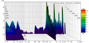
Here are waterfall plots of the arm I'm building. This is with the arm wand hung and hit with a hammer (impulse testing)
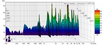
1st plot is the bare arm wand, 2nd plot is with the headshell and CW stub attached. You can see the resonance drops in frequency a bad thing as lower frequencies have greater energy and are more difficult to damp.
Removing the CW will effect arm wand vibration/resonance. At this point it's unclear to me as to the magnitude of this change. It might improve the damping in the wand or it could make it worse, I need to measure the arm I am currently building with both regular CW and mag-lev.
DIY 4 point pivoting arm
Here are waterfall plots of the arm I'm building. This is with the arm wand hung and hit with a hammer (impulse testing)
1st plot is the bare arm wand, 2nd plot is with the headshell and CW stub attached. You can see the resonance drops in frequency a bad thing as lower frequencies have greater energy and are more difficult to damp.
Attachments
I think the plots are reasonable. Other test results with mounted arms show decay times of 40mS. This includes resonance of the pillar assembly and bearings.
Impulse input methods
Structural arm wand resonance (i.e. in all rigid members) will be affected by a) its mass, b) its density variations throughout its mass, and c) its specific geometry. As such waterfall plots can be informative as long as variations in all three of these parameters are accounted for in interpreting such plots. In other words its complicated!
It may be more informative creating waterfall plots to input the physical impulse at the same location, direction and amplitude as a cartridge would do tracking a record groove? Especially if we wish to draw conclusions from making any comparisons.
In particular, if we want to see whether 'Mag-Lev' geometry has any damping effects on structural arm wand resonances visible in the waterfall plots, it may well be necessary to pay such attention to the input set up for the physical impulse and ensure the magnets are in playing position (as it were) - otherwise how else to test for magnet influence on structural damping?
'Mag-Lev' geometry has two variables to tune any potential structural damping (and cartridge / arm mass resonance frequency) by a) magnet repelling force (i.e. bigger / smaller magnets); and b) the length of lever from arm pivots to magnet mounting position.
(Meanwhile, I'm fairly confident 'Mag-Lev' geometry damps the cartridge / arm mass resonance frequency and modifies its waveform c/w a counterweigh).
I think @egellings is referring to the arm wand resonance ... Removing the CW will effect arm wand vibration/resonance. At this point it's unclear to me as to the magnitude of this change. It might improve the damping in the wand or it could make it worse...
Structural arm wand resonance (i.e. in all rigid members) will be affected by a) its mass, b) its density variations throughout its mass, and c) its specific geometry. As such waterfall plots can be informative as long as variations in all three of these parameters are accounted for in interpreting such plots. In other words its complicated!
Fantastic effort, thanks for sharing – those lathe shots reminds me of my basement work shop of decades ago!I need to measure the arm I am currently building with both regular CW and mag-lev.
DIY 4 point pivoting arm
Here are waterfall plots of the arm I'm building. This is with the arm wand hung and hit with a hammer (impulse testing)
It may be more informative creating waterfall plots to input the physical impulse at the same location, direction and amplitude as a cartridge would do tracking a record groove? Especially if we wish to draw conclusions from making any comparisons.
In particular, if we want to see whether 'Mag-Lev' geometry has any damping effects on structural arm wand resonances visible in the waterfall plots, it may well be necessary to pay such attention to the input set up for the physical impulse and ensure the magnets are in playing position (as it were) - otherwise how else to test for magnet influence on structural damping?
'Mag-Lev' geometry has two variables to tune any potential structural damping (and cartridge / arm mass resonance frequency) by a) magnet repelling force (i.e. bigger / smaller magnets); and b) the length of lever from arm pivots to magnet mounting position.
(Meanwhile, I'm fairly confident 'Mag-Lev' geometry damps the cartridge / arm mass resonance frequency and modifies its waveform c/w a counterweigh).
In these waterfall plots the arm was hung by the bearing and the HS end was hit for the wand only all other plots the HS was hit.
Everything that was subsequently attached to the arm wand altered the vibration characteristic of the wand.
All the impulse test tells us is the natural vibration resonance of the arm wand and attached ancillaries, ie what frequencies will be excited in the wand by the cartridge. Attaching a CW to the arm is going to alter this vibration characteristic again.
These were preliminary tests to see what effect different damping materials had on the natural vibration of the arm. I am a great believer in testing in situ so once I have the arm complete I will revisit these tests using the cartridge as the transducer.
Do you have any measurements to support this hypothesis
Everything that was subsequently attached to the arm wand altered the vibration characteristic of the wand.
All the impulse test tells us is the natural vibration resonance of the arm wand and attached ancillaries, ie what frequencies will be excited in the wand by the cartridge. Attaching a CW to the arm is going to alter this vibration characteristic again.
These were preliminary tests to see what effect different damping materials had on the natural vibration of the arm. I am a great believer in testing in situ so once I have the arm complete I will revisit these tests using the cartridge as the transducer.
(Meanwhile, I'm fairly confident 'Mag-Lev' geometry damps the cartridge / arm mass resonance frequency and modifies its waveform c/w a counterweigh).
Do you have any measurements to support this hypothesis
... I am a great believer in testing in situ so once I have the arm complete I will revisit these tests using the cartridge as the transducer. Do you have any measurements to support this hypothesis
Totally agree testing in situ is crucial. Unfortunately I did not formally measure my hypothesis that 'Mag-Lev' geometry damps the cartridge / arm mass resonance frequency and appears to have an asymmetric waveform c/w a counterweigh (beyond observations e.g. the movies you and I have posted links to on this thread - and listening tests confirming BIG sound quality improvements!).
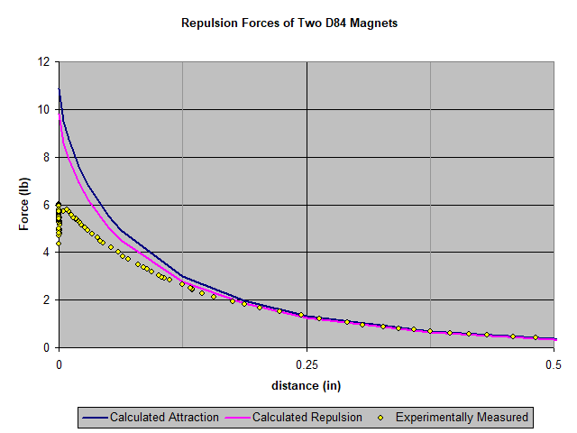
To encourage others here to investigate & experiment, the hypothesis is based on magnetic force obeying an inverse square law with distance. What this means in practical terms is the following:
a) If the distance between two magnets is doubled the magnetic force between them will fall to a quarter of the initial value. (F/4)
b) If the distance between two magnets is halved the magnetic force between them will increase to four times the initial value. (4F)
'Mag-Lev' arm / cart resonances will likely have this asymmetric behaviour (as depicted in the graph below) imprinted upon its wave form.
From rest position (where the magnets are reacting against 100% of the gravity force on the arm mass) the upswing of the arm wand experiences a rapidly decreasing magnetic reaction force dropping at a rate of a quarter of the initial value for a doubling of distance (F/4) being taken over at the peak of the upswing entirely by the gravity force on the arm mass (that's why it falls back down!).
The down swing from the top of the arm wand's swing through its rest position and on downwards, acts like a rapid onset magnetic brake reducing the swing / oscillation amplitude as the force increases at a rate of four times the initial value for a halving of distance. (4F)
Together, these asymmetries must be to some degree imposed upon arm / cart resonance oscillations, and will likely modulate and / or change / and or damp the resonance frequency.
@warrjon this can be tested on your existing 'Mag-Lev' rig - wind a dozen turns of insulated copper wire around the stationary magnet. Connect the wires to a storage oscilloscope or a lap top 'scope app. The resonance oscillations should be visible when the arm is bounced up and down.
Repelling Magnets
Last edited:
- Home
- Source & Line
- Analogue Source
- Tone arm improvements - no counter-weight (pseudo) magnetic levitation