I am using 94V power supplies (one per channel) and low-speed, low-noise fan cooling. The fans run at about 600RPM, with heatsink temperatures of less than 45C directly under the SITs. Below are some pictures:
Anther of your fugly (compliment) Borg cubes.
150w/ch at idle. Massive.
Is that an IXYS hockey puck serving as the CCS? Which one?
Sorry if I missed a thread where you shared this info.
The CCS uses an IXYS IXFN140N30P. The total power into the transformer is 2.9A at 120VAC = 348W.
I use this fugly packaging because it requires very little machining, allows fan cooling if needed, and make adjustments and board removal simple.
I use this fugly packaging because it requires very little machining, allows fan cooling if needed, and make adjustments and board removal simple.
Anther of your fugly (compliment) Borg cubes.
150w/ch at idle. Massive.
Is that an IXYS hockey puck serving as the CCS? Which one?
Sorry if I missed a thread where you shared this info.
The CCS uses an IXYS IXFN140N30P. The total power into the transformer is 2.9A at 120VAC = 348W.
I use this fugly packaging because it requires very little machining, allows fan cooling if needed, and make adjustments and board removal simple.
Just like a Cray supercomputer. It puts you in very good company.
Thank you for sharing your parts choices and operating voltage and current. It will help me as I get acquainted with the Tokin SIT. I bet some other people will get some inspiration from your work as well.
In order to obtain the proper sweet spot, the operating voltage appears to be highly dependent on the individual SIT, and the desired output power. It requires measuring the THD of the SIT at various choices of bias current, Rmu (the mu-follower resistor providing the modulation to the current source), and SIT Vds.
Got it. Thank you for sharing your experience. If you want two closely matched channels, it seems a large population of parts would be required.
Presently trying some enhancement P-channel devices with the Tokin SIT in a DEF arrangement at different supply rails. It would be nice to have a wide selection of P devices to choose from.
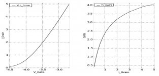
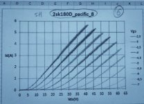
TOKIN SIT Gain Curve
This is something that modern (digital data) curve tracers can do. The data is in a spreadsheet. Exact values of Vgs and gain at any particular Ids can be interpolated from the data.
I wanted to know the gain at of this Tokin SIT at 24V Vds at 1.5A Ids to start matching to P channel MOSFETs for a DEF output stage. Vgs at 1.5A Ids is ~ -3.7V and Gain is ~ 2.8.
Attachments
Gain means transconductance ?
Yes. I should probably re-name the formula result as transcunductance to eliminate confusion.
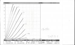
.. a pair of Tokin SITs to curve trace.
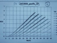
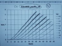
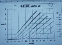
My 2SK180 Tokin curves was made by member Jama.
He used Frankentracer with software
Attachments
-
 04C3F234-1CAA-4A71-9645-569971A1B187.JPG423.1 KB · Views: 519
 -
 9F0C546E-8BBB-4642-9659-351EE8366B5A.JPG511 KB · Views: 487
 -
 608753F8-1FCF-495E-89D0-E876C641B285.JPG500.4 KB · Views: 479
 -
 168C2DCD-062A-436B-B4A9-23AF59A59861.JPG370.6 KB · Views: 481
 -
 B03EF014-0CEA-4F3F-B936-54BDB272BB89.JPG341.5 KB · Views: 468

Curve tracer software by Mr. Rothacher download link Frankentracer Excel Capture | AudioMaker
This lash-up is very clever and very cool. If I needed to brew one, I would use this. The curve tracers from the 1960s - 1970s used this technique and cost upwards of $40,000 back then. Many are still in use. I have seen them in my travels for my day job.
for us old farts toob guys - there was no puzzle
µ=S x Ri
🙂
µ is gain
S is transconductance in mho or microsiemens.
Ri Resistance of D in SIT, in vacuum tubes is Ri of Anode.
this is an ohm law but dynamic one.
µ is E
S is I and
Ri is R.
I guess if not remember as you my dear Aleksandar
@ GnuB
Great triode curves Something like big 845, 211 tubes but transistor version equivalent 🙂
Great triode curves
Something like big 845, 211 tubes but transistor version equivalent 🙂

- Home
- Amplifiers
- Pass Labs
- Tokin SIT low voltage high current curves