Sonnya,
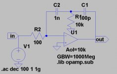
you should swap the values of C1 and C2 (or swap the
components themselves). I know I caused a bit of confusion
on this previously, I am sorry for that.
you should swap the values of C1 and C2 (or swap the
components themselves). I know I caused a bit of confusion
on this previously, I am sorry for that.
It seems this discussion died out, so I take it that two-pole
compensation is not very common and nobody has any
experience with it, or...?
Sonnya, do I understand you correctly that you also came to
the conclusion that the method seems to work well if judging
from simulations? Unfortunately, I never saved any results of
my simulations.
compensation is not very common and nobody has any
experience with it, or...?
Sonnya, do I understand you correctly that you also came to
the conclusion that the method seems to work well if judging
from simulations? Unfortunately, I never saved any results of
my simulations.
Yes, if you are able to get a phasemargin of 50 degrees i can see a benefit from it. I do not like to get closer to 180 degrees phaseshift than that! 😉
By the way Douglas self writes in his book "The Audio Power Amplifier Design Handbook. Third edition" when i he applies two pole compensation to his Class B or G circuits. Crossover artifacts nearly dissapears!!!!
It is a good book by the way
By the way Douglas self writes in his book "The Audio Power Amplifier Design Handbook. Third edition" when i he applies two pole compensation to his Class B or G circuits. Crossover artifacts nearly dissapears!!!!
It is a good book by the way
traderbam wrote:
What causes the VAS output pole that you show?
Why does the non-miller cap curve coincide with the miller cap curve at the closed loop gain point - is this a coincidence?
-------------------------
a)VAS output resistance, output stage input resistance, output stage (driver) input capacitance
b) the open-loop curve coincide with the miller cap curve at the closed loop gain point because you don’t need to make miller cap higher to get lower closed loop –3dB frequency
capslock wrote:
Well, actually a lot of Elektor designs used roll-off in the input stage. It was a cap in series with a rather small resistor connected between the collectors of the input pair. It worked because the first diff pair only drove another diff pair which then drove the VAS.
--------------------
I use this RC roll-off usually when I use discrete BJT/FET input stage and opamp. The input stage is optimized for the best noise behaviour, for example in RIAA stage I use p-n-p BJT with 100 uA collector current. Then I put 1kOhm trimmer and big elco, trimmed for the nice response with closed loop, then replace elco by a small ceramic one several times to obtain small overshot.
christer wrote:
It seems this discussion died out, so I take it that two-pole
compensation is not very common and nobody has any
experience with it, or...?
-------------
Try to find data sheet for National 20 years old LM101/201/301 op amp. There are frequency response curves for two pole compensation. I still think that 301 and 2-pole is still great for audio (please don’t kick me) you should add only 2.2 k between output and negative supply rail to switch op-amp output stage in class A
dimitri said:Try to find data sheet for National 20 years old LM101/201/301 op amp. There are frequency response curves for two pole compensation. I still think that 301 and 2-pole is still great for audio (please don’t kick me) you should add only 2.2 k between output and negative supply rail to switch op-amp output stage in class A
The datasheet was still available and shows examples of
single-pole, two-pole and feed-forward compensations.
Thanks.
a)VAS output resistance, output stage input resistance, output stage (driver) input capacitance
Ok, that's what I thought. This "pole" will not be static because these parameters will vary with voltage, current and load Z. The Miller cap will act to stabilize the open loop roll-off and counteract the variation of these parameters.
In your earlier post you discussed different arrangements for the cap such as from output to VAS input. The problem I see is that the stability is compromised in these alternative arrangements. Ultimately, we could agree that putting a cap from output to inverting input puts the maximum feedback around the system, but this would typically result in an unstable system.
Have you found a way to either eliminate the miller cap or apply the cap in a more optimum place and achieve better performance with equal stability?
traderbam wrote:
In your earlier post you discussed different arrangements for the cap such as from output to VAS input. The problem I see is that the stability is compromised in these alternative arrangements.
-------------------
This is exactly so. I made a lot Cherry-style compensation, but the second pole remains unchanged and I put RC network to ground at the VAS output to make second pole time constant lower, but at the expence of gain :-(
traderbam wrote:
Have you found a way to either eliminate the miller cap or apply the cap in a more optimum place and achieve better performance with equal stability?
-------------------
In this particular arrangement - LTP, VAS, output buffer it is superior (yes it should be modified fr two-pole compensation CRC network, or by three-pole CLC network ...)
capslock said:Can you explain a little more about two-pole compensation?
see:
http://www.diyaudio.com/forums/showthread.php?s=&threadid=14482&perpage=15&pagenumber=3
..from post #40 etc..etc..
- Status
- Not open for further replies.
- Home
- Amplifiers
- Solid State
- to Miller compensate or not to Miller compensate