Great work! Do you have the analog volume control going to a volume pot on the front of the amp that cannot be seen in your photo? Why not move the motorized pot to the front panel so you can do both - remotely and manually? Am I missing something in your intended design? I haven't started my build, so maybe I haven't read far enough yet. 🙂Dear SYMASYM-friends,
I have started and married the "Black-Beauty - SYMASYM" (which is in fact green in my prototype-case) with my auxiliary "DC-Mains-Filter, Soft-Power-On, Digital PSU - and RPre - PCB".
Everything works as designed so far, but I have to re-program the PIC-processor to be able to show all the information that it is able to show on a single 1x16 chars display.
"In my hunble opinion": I could not have this done better!
Best regards - Rudi_Ratlos
I can see in the picture the motorized pot laying somewhere down on chassis. I'm sure the pot will be installed on front panel.
@Rudi - you moved from Bourns to Alps ? They have a better resistence consinstency ?
@Rudi - you moved from Bourns to Alps ? They have a better resistence consinstency ?
Last edited:
I started with Pavel's values and adjusted slightly.Andrew I heard that you have a different of Pavel's, but elegant solution for Toshiba' SymAsym oscillation, could you please share it? Thank you.
But I'm not finished.
I want to post .asc of Pavel's and standard and my current and ask for help in determining the stability margins of all three.
Until I have reached this stage, it's too early to say what the final compensation might look like.
Yeah, I saw the motorized one laying there, but just didn't want to assume too much. When I saw the connector labeled analog attenuation with a red and white wire, I couldn't find the other end, so wondered if there was another pot somewhere. Silly me. 🙂I can see in the picture the motorized pot laying somewhere down on chassis. I'm sure the pot will be installed on front panel.
@Rudi - you moved from Bourns to Alps ? They have a better resistence consinstency ?
Put me down for two (2) pairs
> If you would like to have a pair them (along with the matching PCB): please transfer > 29€ to my PAYPAL-ID: RRozek@t-online.de
Put me down for two (2) pairs. Let me know what the total will be. Take care.🙂
> If you would like to have a pair them (along with the matching PCB): please transfer > 29€ to my PAYPAL-ID: RRozek@t-online.de
Put me down for two (2) pairs. Let me know what the total will be. Take care.🙂
Mr. Rudi Sir,, I,ve received the black beauties pcb,s WOW WHAT AN UNDER STATEMENT
I,m afraid to solder them, These pcb,s take your breath away..THANK YOU THANK YOU,
WOWwwwwwwwwwwwwwwwwwwww evette
I,m afraid to solder them, These pcb,s take your breath away..THANK YOU THANK YOU,
WOWwwwwwwwwwwwwwwwwwwww evette
Hopefully, mind will arrive soon now, knowing you're in Canada. I'm in the states and been waiting for over a couple of weeks now. 🙁 Can't wait to get my hands on them too.Mr. Rudi Sir,, I,ve received the black beauties pcb,s WOW WHAT AN UNDER STATEMENT
I,m afraid to solder them, These pcb,s take your breath away..THANK YOU THANK YOU,
WOWwwwwwwwwwwwwwwwwwwww evette
Gentlemen,
I have taken a holiday in the past days and returned home today.
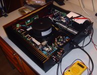
Rick, Adrian: since all the functions (Power On/Off, attenuation, source selection, ...) can be controlled via a remote control unit, I do not need a switch, neither do I need a knob on the front panel.
This is the reason why I have installed the motorized dual potentiometer into the case.
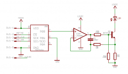
But this potentiometer looks like (is) a real anachronism, and I would like very much to replace it by a "digital potentiometer" (MCP4151, which has 128 wiper steps) followed by a VCCS (see attached image 1).
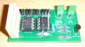
I have already done a layout for this schematic and have etched and populated two of the resulting PCBs (see attached image 2).
I am using simple LEDs instead of LDRs on this "evaluation-PCB".
My problem: I am no good at programming a PIC - µProcessor in "C".
I have been programming IBM-mainframes in Assembler for more than 35 years of my life, but now, when I program a PIC in "C", I get lost and desperate, if I forgot to insert a ";" or a "}" into the code.
I am of course able to change the existing VCPre's code (whose inital programming has been done by METAL), if required, but implementing a new function, ...?
If there is anybody among you (I am sorry that Paul does not have the time), who has the time to assist me, who knows the internals of the PIC16F887 and has a PIC-evaluation board and who knows,
how to program it in "C" (for example the SPI-interface): I will happily send him one of the two evaluation PCBs and will program together with him the digital potentiometer interface.
And of course I will send him a couple of the resulting Pre - PCBs (see my P.P.S.).
Best regards - Rudi_Ratlos
P.S.: I am currently not having any "Black-Beauty SYMASYM" - PCBs anymore. Maybe I will order a small couple of them in a month or so.
Ryan, Rick; please have some patience. Your PCBs will definitely arrive soon.
P.P.S.: I will also post this reply in my "PRE - thread": http://www.diyaudio.com/forums/group-buys/237302-versatile-comfortable-passive-pre-amp.html
I have taken a holiday in the past days and returned home today.
Rick, Adrian: since all the functions (Power On/Off, attenuation, source selection, ...) can be controlled via a remote control unit, I do not need a switch, neither do I need a knob on the front panel.
This is the reason why I have installed the motorized dual potentiometer into the case.
But this potentiometer looks like (is) a real anachronism, and I would like very much to replace it by a "digital potentiometer" (MCP4151, which has 128 wiper steps) followed by a VCCS (see attached image 1).
I have already done a layout for this schematic and have etched and populated two of the resulting PCBs (see attached image 2).
I am using simple LEDs instead of LDRs on this "evaluation-PCB".
My problem: I am no good at programming a PIC - µProcessor in "C".
I have been programming IBM-mainframes in Assembler for more than 35 years of my life, but now, when I program a PIC in "C", I get lost and desperate, if I forgot to insert a ";" or a "}" into the code.
I am of course able to change the existing VCPre's code (whose inital programming has been done by METAL), if required, but implementing a new function, ...?
If there is anybody among you (I am sorry that Paul does not have the time), who has the time to assist me, who knows the internals of the PIC16F887 and has a PIC-evaluation board and who knows,
how to program it in "C" (for example the SPI-interface): I will happily send him one of the two evaluation PCBs and will program together with him the digital potentiometer interface.
And of course I will send him a couple of the resulting Pre - PCBs (see my P.P.S.).
Best regards - Rudi_Ratlos
P.S.: I am currently not having any "Black-Beauty SYMASYM" - PCBs anymore. Maybe I will order a small couple of them in a month or so.
Ryan, Rick; please have some patience. Your PCBs will definitely arrive soon.
P.P.S.: I will also post this reply in my "PRE - thread": http://www.diyaudio.com/forums/group-buys/237302-versatile-comfortable-passive-pre-amp.html
Attachments
Last edited:
Thanks for the clarification Rudi. I know you had mentioned in an earlier post about a digital pot, so I will follow with interest those developments. I just wasn't sure if the motorized pot was fully installed inside, or just laying there temporarily. However, even with a remote controlled pot, I still like manual access on the front of an integrated amp too.Gentlemen,
I have taken a holiday in the past days and returned home today.
Rick, Adrian: since all the functions (Power On/Off, attenuation, source selection, ...) can be controlled via a remote control unit, I do not need a switch, neither do I need a knob on the front panel.
This is the reason why I have installed the motorized dual potentiometer into the case.
But this potentiometer looks like (is) a real anachronism, and I would like very much to replace it by a "digital potentiometer" (MCP4151, which has 128 wiper steps) followed by a VCCS (see attached image 1).
I have already done a layout for this schematic and have etched and populated two of the resulting PCBs (see attached image 2).
I am using simple LEDs instead of LDRs on this "evaluation-PCB".
My problem: I am no good at programming a PIC - µProcessor in "C".
I have been programming IBM-mainframes in Assembler for more than 35 years of my life, but now, when I program a PIC in "C", I get lost and desperate, if I forgot to insert a ";" or a "}" into the code.
I am of course able to change the existing VCPre's code (whose inital programming has been done by METAL), if required, but implementing a new function, ...?
If there is anybody among you (I am sorry that Paul does not have the time), who has the time to assist me, who knows the internals of the PIC16F887 and has a PIC-evaluation board and who knows,
how to program it in "C" (for example the SPI-interface): I will happily send him one of the two evaluation PCBs and will program together with him the digital potentiometer interface.
And of course I will send him a couple of the resulting Pre - PCBs (see my P.P.S.).
Best regards - Rudi_Ratlos
P.S.: I am currently not having any "Black-Beauty SYMASYM" - PCBs anymore. Maybe I will order a small couple of them in a month or so.
Ryan, Rick; please have some patience. Your PCBs will definitely arrive soon.
P.P.S.: I will also post this reply in my "PRE - thread": http://www.diyaudio.com/forums/group-buys/237302-versatile-comfortable-passive-pre-amp.html
I'm not worried about the PCBs and other parts. I'm sure they'll show up soon.
Rick
However, even with a remote controlled pot, I still like manual access on the front of an integrated amp too.
Rick
I can replace that motor with a rotary encoder so you still have a direct physical interface. I and Rudi will talk about it to see what can be done.
Would be great end result to be a pot replacer as i have two ldr preamps from Rudi.
Sent from my iPad using Tapatalk
Sent from my iPad using Tapatalk
Hi Rudi,
My package of PCBs and parts showed up today. Thanks! The boards are gorgeous. I certainly don't want to muck them up accidentally. I'll be extra careful with my parts placement and soldering for sure. I'll PM you later about the other small bag to be sure I know what to do with them.
Thanks again,
Rick
Dear SYMASYM-friends,
I have had some time yesterday and have adjusted the quiescent current of my current SYMASYM - build (the left channel - without using the light-bulk delimiter anymore).
I have measured the DC-offset on the output during the adjustment phase.
There is no DC-offset at all. Andrew_T will appreciate.
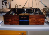
I will go on with the right channel today and do some thinking about the case's front panel.
Best regards - Rudi_Ratlos
P.S.: Before you ask me: I am using a Wall-Market speaker-cable (1 meter costs 3€) and RG59 - RCA - cable for internal wiring.
Maybe the lettering is too big.
I have had some time yesterday and have adjusted the quiescent current of my current SYMASYM - build (the left channel - without using the light-bulk delimiter anymore).
I have measured the DC-offset on the output during the adjustment phase.
There is no DC-offset at all. Andrew_T will appreciate.
I will go on with the right channel today and do some thinking about the case's front panel.
Best regards - Rudi_Ratlos
P.S.: Before you ask me: I am using a Wall-Market speaker-cable (1 meter costs 3€) and RG59 - RCA - cable for internal wiring.
Maybe the lettering is too big.
Attachments
Last edited:
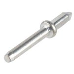
1.3mm Soldering Pins?
Could you post a picture of what a 1.3mm soldering-pin looks like that is used in your VCPre? I assume they are individual vertical pins, rather than some type of connector. What do they look like?
Thanks.
Similar to this?
Could you post a picture of what a 1.3mm soldering-pin looks like that is used in your VCPre? I assume they are individual vertical pins, rather than some type of connector. What do they look like?
Thanks.
Similar to this?
Attachments
Last edited:
Great. Thanks. Those I don'the have in my hardware supply so need to order some. 🙂Rick: your image shows is exactly what I call "soldering-pin".
Best regards - Rudi
- Home
- Group Buys
- TO-3 SYMASYM