
Gentlemen,
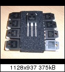
I am very proud to offer you 4 pairs of matched NJW0281G / NJW302G.
http://www.abload.de/img/joe012t6joq.jpg
They have been matched by my Canadian friend Joseph, they have a very small internal capacitance
(COB of 400pf only - the MJE drivers will love them),
they are absolutely new and authentic OnSemi - and they will fit perfectly into your SYMASYM PCB.
I will offer you these 8 transistors for 24€.
The first, who says that he wants to have them, gets them.
Best regards - Rudi_Ratlos
I am very proud to offer you 4 pairs of matched NJW0281G / NJW302G.

http://www.abload.de/img/joe012t6joq.jpg
They have been matched by my Canadian friend Joseph, they have a very small internal capacitance
(COB of 400pf only - the MJE drivers will love them),
they are absolutely new and authentic OnSemi - and they will fit perfectly into your SYMASYM PCB.
I will offer you these 8 transistors for 24€.
The first, who says that he wants to have them, gets them.
Best regards - Rudi_Ratlos
Gentlemen,
I am quite surprised that nobody of you showed interest in my offer of 4 pairs of matched NJW0302/NJW0281 transistors for the SYMASYM so far.
This is part of the NJW0 - specifications:
Features
•Exceptional Safe Operating Area
•NPN/PNP Gain Matching within 10% from 50 mA to 3 A
•Excellent Gain Linearity
•High BVCEO
•High Frequency
•These are Pb-Free Devices
So: any pair of NJW0 - transistors that you buy is Hfe-matched within 10% by fabrication process.
The ones that I offer you are matched within <<5%.
You can even substitute the emitter resistors by 0R1 - types: you will only hear 1 (!) transistor playing,
being able to dissipate a total power of 300 Watts.
And yes: there is a noticeable, audible difference between output transistors with a Cob of 650pF (f.e. MJL4xxx; the drivers have to
unload this capacitance during each swing) and the NJW0 - type, which has a Cob of 400pF only.
It is your choice, gentlemen, which output transistors you will use.
I do not recommend you to use Toshiba 2SC / 2SA, since the Toshibas have a tendency to oscillate using the underlying
version 5.3 schematics of the SYMASYM (see PAVELs page: symasym).
Best regards - Rudi_Ratlos
Hi Rudi, for me please
2x TO-264 SYMASYM PCB - the price is 8.50€ per PCB
2x Speaker Protection PCB - the price is 5€ per PCB
2x PSU PCB - the price is 9€ (this new (!) PSU PCB will accommodate caps with a diameter of 35 mm)
2 Sets Emitter-resistors - the price is 2.50€ for 4 Futaba MPC74 0R22 resistors
4 Pairs Output-transistors - the price is 9€ for 2 pairs of NJW0281 / NJW0302
2x Input-Cap - the price is 3€ for one Vishay MKT1822
Thanks
Claus1968
Gentlemen,
this group-buy is closed now.
This is the final order-EXCEL-sheet:
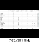
http://www.abload.de/img/image10y5xm.png
I already ordered the input caps and emitter-resistors.
Regarding the PCBs:
Most of you know already, that the lead time for the PCB order is 12 days.
This time it will take one week longer.
The chinese etching company writes:
We will have Chinese Spring Festival holiday from Jan 22 to Jan 28, 2012.
I think it will take a least 3 weeks, until the PCBs will be etched.
I will inform you about the progress.
In one of the next days I will send to those of you, who do not yet have, the TO264-SYMASYM Builder's Manual.
Inside you find the schematics, instructions how to build, how to adjust the quiescent current, the BoM,...
Best regards - Rudi_Ratlos
This is the 1st picture of the DX PSU - Rev.2 - PCB that METAL and I will offer in this group-buy.
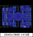
http://www.abload.de/img/psu9srjt.png
My German DIY-friends tend to forget the power-dissipation of the rectifier-diodes, when they drive their SYMASYM
from one > 300 Watt transformer and one PSU-PCB (due to space limitations).
We therefore provided room for a big heatsink for the rectifier diodes.
The reservoir capacitors can have a diameter up to 35mm, clipped in with 10mm grid.
Best regards - Rudi_Ratlos
Gentlemen,
the PCBs are due to arrive the week of Feb. 8th.
I will ship them out immediately after their arrival.
The letters are already prepared.
Sorry for the delay. It has been due to "New Year's Holiday" in China.
I will send to you all the "TO-264 Builder's Manual" in a minute.
Best regards - Rudi_Ratlos
Patrick,
there is nothing "great" about this news.
It simply says: "Gentlemen, don't get impatient please! You will receive the PCBs of a very, very good sounding amplifier in a week or two".
I am sorry for the delay.
Best regards - Rudi
there is nothing "great" about this news.
It simply says: "Gentlemen, don't get impatient please! You will receive the PCBs of a very, very good sounding amplifier in a week or two".
I am sorry for the delay.
Best regards - Rudi
Gentlemen,
I am happy to tell you that the PCBs have been etched today and are already on their way to me.
Here is the URL of the tracking ID:
DHL | Tracking | English
if you like to follow their way.
Best regards - Rudi
I am happy to tell you that the PCBs have been etched today and are already on their way to me.
Here is the URL of the tracking ID:
DHL | Tracking | English
if you like to follow their way.
Best regards - Rudi
Gentlemen,
I received the PCBs today:
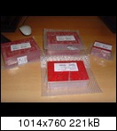
http://www.abload.de/img/joe019mluo6.jpg
(they are flawless as usual)
and will dispatch them tomorrow.
You all will have them in your hands in the course of next week.
I wish you a nice build and a nice sound!
Best regards - Rudi_Ratlos
I received the PCBs today:

http://www.abload.de/img/joe019mluo6.jpg
(they are flawless as usual)
and will dispatch them tomorrow.
You all will have them in your hands in the course of next week.
I wish you a nice build and a nice sound!
Best regards - Rudi_Ratlos
So did I, very good quality!!!
Should we make a new thread for these boards? I will start building a Symasym and I have some questions I would like to ask, have lots of compatible parts and I would like to hear other opinions regarding them. Also I was wondering if it's possible to use higher voltage rails and what components need to be upgraded...?
Should we make a new thread for these boards? I will start building a Symasym and I have some questions I would like to ask, have lots of compatible parts and I would like to hear other opinions regarding them. Also I was wondering if it's possible to use higher voltage rails and what components need to be upgraded...?
Butch,
I do not think that it is necessary to open an extra builder's thread.
Since the group-buy is closed, you can use this thread to post your thoughts / questions in here.
Yes: you can of course raise the rail-voltages! You are even welcome to do this!
EVETTE did this as well and is absolutely content with the results.
Be aware of the value of the rail-capacitors C16 and C17 then!
And do not forget and activate the cap-multiplier with the ZENER.
Best regards - Rudi
Last edited:
Thanks Rudi, I'll examine the schematics and see what can be easily upgraded.
Can you tell me what was the max voltage for Symasym, that worked stable?
I am fimiliar with Rod's capacitance multiplier but I have no idea what you mean by "activate the cap multiplier with the zenner". I feel a bit rusty now, need to do some reading to remember few things.
My main question is about the LEDs present on the PCB, not sure what are they for.
Cheers,
Vlad
Vlad,
the LEDs simply reflect the status of the power rails.
If they burn, it means: power rail voltage is present. So the LEDs should burn all the time.
I have added a jumper (two jumpers) on the PCB to bypass or not the cap-multipliers for the positive and negative rail.
If the jumper is set (activated), the cap-multiplier will be bypassed and the frontend will be powered by the backend PSU (voltage).
But take care then: if you drive the AMP from a 30 VAC PSU (f.e.), this may blow the sensitive input transistors!
If the jumper is not set, the cap-multiplier is activated.
It includes a ZENER diode to limit the voltage for the frontend to a value that is convenient (f.e. 39V) and will prevent any harm
to the input transistors, even if you drive the backend with a higher voltage.
Best regards - Rudi
- Home
- Group Buys
- TO-3 SYMASYM