Gentlemen, I will be able to offer you lower prices due to quantity discount.
I will also order FUTABA MPC74 0R22 emitter-resistors.
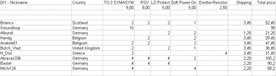
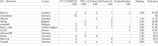
Find attached the current order list.
Please transfer the total amount of money to my PAYPAL ID: RRozek@t-online.de
I would like and order the PCBs on Monday, 12th of March.
Best regards - Rudi
I will also order FUTABA MPC74 0R22 emitter-resistors.
Find attached the current order list.
Please transfer the total amount of money to my PAYPAL ID: RRozek@t-online.de
I would like and order the PCBs on Monday, 12th of March.
Best regards - Rudi
Attachments
Rudi
I have a very simple automatic fan control schematic that works really well. Is there any chance you can make a few PCB's for that?
The fan speed increases with the temperature, when first powered on the fan runs at full speed for 1 second(you need to add 1 capacitor 1000uf/25v in parallel with the NTC)
Temperature-controlled 12V dc Fan - RED - Page109
I think this would be a circuit that many need inside their amplifiers
Regards,
Vlad
Butch,
you asked me:
"I have a very simple automatic fan control schematic that works really well. Is there any chance you can make a few PCB's for that?"
Of course I can do this.
I will do it over the weekend and show it do you.
Best regards - Rudi
you asked me:
"I have a very simple automatic fan control schematic that works really well. Is there any chance you can make a few PCB's for that?"
Of course I can do this.
I will do it over the weekend and show it do you.
Best regards - Rudi
😀😀: Sound like a plan Rudi
Let me know if you need more info
PS: I like your group buy 🙂, I don't really need the PCB's but they look so good I can't resist buying some😎
Let me know if you need more info
PS: I like your group buy 🙂, I don't really need the PCB's but they look so good I can't resist buying some😎
I would like to run this amp (with this board) from a 28-0-28 VAC transformer (because that's what I have.) I know the specified value is 25-0-25 VAC, and that the original symasym (e.g. AAKs) can run up to 50V rails, 35-0-35 transformer).
Can someone tell me the tweaks to the Cap-multiplier circuit I would need to make, to ensure safe operation at the increased voltage. I did read the assembly guide (or rather had it translated via Google) but it was unclear to me what changes must be made.
Thanks for your time.
Ryan
Can someone tell me the tweaks to the Cap-multiplier circuit I would need to make, to ensure safe operation at the increased voltage. I did read the assembly guide (or rather had it translated via Google) but it was unclear to me what changes must be made.
Thanks for your time.
Ryan
Ryan,
a transformer with 2 x 28VAC secondaries will give you about +/- 39VDC (roughly) after rectification.
Please take in account deviations in mains voltage, ..., as well.
This voltage may be critical for "sensitve" input transistors, like the 2SK170.
I therefore recommend you to solder the cap-multiplier and use a Z036 Zener-diode so that the frontend's voltage will be delimited to 35.3V (roughly).
And please: use 50VDC rail capacitors.
You should not have any problems then.
Best regards - Rudi
Whilst the subjects at the moment are Tx and cooling, I have been trying to find info. on the suggested PS requirements before the board. I would like to know the suggested VA rating for both two Tx PS and Single Tx. Also would like to know the recommended heatsinks for this amp, preferably by a makers code and measurement. [I will be aiming at building a totally standard stereo-amplifier.]
Many thanks,
Brian
Many thanks,
Brian
Brian,
I advise you to get either 1 transformer 2X25 VAC rated at 300W and 1 PSU-PCB (this is the standard stereo-implementation) or 2 2X25VAC transformers rated at 200W each and 2 PSU-PCBs (which is what I call: Dual-Mono).
The heatsink should be about 0.7 - 0.8 k/W, for example this one:
Strangkühlkörper Typ SK 85 Fischer Elektronik SK 85 (B x H x T) 160 x 40 x 100 mm R(th) 0.85 K/W im Conrad Online Shop
Best regards - Rudi_Ratlos
Rudi
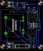
PCB looking good
Few things to consider: most fans need ~200ma to operate and PCB transformers are wery low power. Maybe is better to have a chassy mounted trafo instead of PCB ? Two decent fans require 0.5A minimum (depends on the max RPM).
Maybe consider some jumpers to solve the routing issue? Don't think anyone would mind a couple of wire jumpers on the pcb 🙂
Don't forget the 1000/25v capacitor parallel with the thermistor (I think that is on the PCB already but I am not sure 🙂 )
Regarding the zenner diode for the front end of the amplifier (35 or 39v ?) can you post a photo with the position where it should be located? Can we substitute the small transistors with some higher voltage equivalents (pin to pin compatible preferable) to avoid overvoltage issues?
Cheers,
Vlad
@Butch_Vlad,
I don't want to mix this thread with fan-control considerations.
Please give me your EMail-adress (send me PM) and we will go on per EMail.
Best regards - Rudi
P.S. The EI48 - PCB transformer I have in mind can provide 700mA @ 12VAC.
I don't want to mix this thread with fan-control considerations.
Please give me your EMail-adress (send me PM) and we will go on per EMail.
Best regards - Rudi
P.S. The EI48 - PCB transformer I have in mind can provide 700mA @ 12VAC.
- Home
- Group Buys
- TO-3 SYMASYM