We cannot advise until you post the schematic.fossil2k said:Should I shunt the inputs & output with resistors is 1 op-amp is not used in a dual op-amp package??
"Should I shunt the inputs & output with resistors is 1 op-amp is not used in a dual op-amp package??"
On unused opamp sections I ground the non-inverting input and hook the inverting input to the output, no resistors required.
On unused opamp sections I ground the non-inverting input and hook the inverting input to the output, no resistors required.
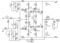
Sorry guys, in the earlier post I've asked for suitable replacement for LM339 but after obtaining the schematic of my amplifier a few days ago, I've found that it is used in the protection circuit. Anyhow, I have made some modifications to my amplifier.
1. Bypass the selector switch by connecting directly the RCA socket to the volume control and to the amplifier circuit using silver wire.
2. Changing the aged capacitors in the circuit with those from WIMA & Panasonic.
3. Changing NE5534 with OPA2134/NJM2114 with BG caps across its supply.
After comparing both chips, 2134 gives solid image but I find that the bass a bit too much. Whereas the 2114 gives more balance sound but not solid. Anymore chips that I could use? As my CD63 is upgraded before with AD8065 & BG caps, I was thinking of using the same chip as well.
Somewhere in the forum, I have read that there is some low noise transistors. Is it true?? I have attached the schematic and maybe you guys can give some comments. Thanks.
Attachments
Use a TLE-2074
TI has come out with an enhanced replacement to the TLO-84.
It is the TLE-2074. This opamp part of their Excalibur series, possessing lower noise and distortion and higher gain bandwidth product and slew rate. They are VERY good sounding opamps.
They also make singles (TLE2071) and duals (TLE2072).
Also, National Semiconductor now has a quad high performance audio opamp-the LME49740. It is essentially a second generation quad version of the LM4562 dual. They also have singles (LME49710) and duals (LME49720). If you use these opamps, make sure that you have sufficient power supply bypass capacitors installed, as these units have the ability to become great oscillators without them.
If you use these opamps, make sure that you have sufficient power supply bypass capacitors installed, as these units have the ability to become great oscillators without them. (dpuopolo)
Can you explain the power supply bypass capacitor? Mine have a 0.47uF NP across its supply and sitting on top of the op-amp.
Can you explain the power supply bypass capacitor? Mine have a 0.47uF NP across its supply and sitting on top of the op-amp.
fossil2k said:Can you explain the power supply bypass capacitor? Mine have a 0.47uF NP across its supply and sitting on top of the op-amp.
Local bypass, very close to the power pins, with something like 47uF or so, with good quality caps, may be necessary too, besides the film type bypass. I must confess I am not too much a fan of ceramics, even if some types seem to work quite well in audio projects.
The 0.47uF BG cap is recommended by a local DIY shop that claims to improve the sound. My next problem if you look at the schematic is what type of cap to replace at the input of the op-amp.
My next project would be building a KWAK clock for my CD63 but not sure if the schematic I got is correct.
My next project would be building a KWAK clock for my CD63 but not sure if the schematic I got is correct.
You have to have caps from each power supply pin to ground.
I usually use .1's, but .47's should also be fine. It's not necessary to put a capacitor between the two power supply pins; in fact it might be detrimental.
I usually use .1's, but .47's should also be fine. It's not necessary to put a capacitor between the two power supply pins; in fact it might be detrimental.
Also, can you guys recommend the brand for each type of caps that is good??polyester?electrolytic?ceramic?etc?
Yes, a cap from each power supply pin (+ -) to ground. Make the leads as short as possible.
Cap preference in this order:
Polycarbonate, mylar, ceramic disk, tantalum, electrolytic.
The best value for a bypass is mylar. They work fine and are cheap. Even Radio Shack will sell you two .22 50 volt mylars for $1.49. These are completely suitable and I use them frequently.
http://www.radioshack.com/product/i...&cp=2032058.2032230.2032267&parentPage=family
I have got some Mylar from Panasonic. Maybe will try this during the weekend.
Another question on the op-amp, it is running at half of its rated voltage but it becomes hot after 1hr. Could it cause by the 2nd internal op-amp not being grounded?
Another question on the op-amp, it is running at half of its rated voltage but it becomes hot after 1hr. Could it cause by the 2nd internal op-amp not being grounded?
You need to 'turn off' unused amplifiers by connecting their output to their inverting input and then connecting their non inverting input to ground. This is ESSENTIAL!
Post #22
"Should I shunt the inputs & output with resistors is 1 op-amp is not used in a dual op-amp package??"
On unused opamp sections I ground the non-inverting input and hook the inverting input to the output, no resistors required.
__________________
"Should I shunt the inputs & output with resistors is 1 op-amp is not used in a dual op-amp package??"
On unused opamp sections I ground the non-inverting input and hook the inverting input to the output, no resistors required.
__________________
Thanks for the advise. For the quad chip, I did not change them. As said earlier, I finally get a copy of the amp schematic and found that it is used for protection circuit, therefore I did not bother to change them. I will try the grounding of the op-amp and see if it will become hot..
I'm still looking at changing the op-amp. I have tried AD8065 on my CDP and find that the sound is good. I was recommended LME49710 but the price USD25 compare to USD6 for AD8065..
I'm still looking at changing the op-amp. I have tried AD8065 on my CDP and find that the sound is good. I was recommended LME49710 but the price USD25 compare to USD6 for AD8065..
Hi,fossil2k said:What is the best replacement for polystrene & stack foil capacitors??
what do you want to use either of these for???
- Status
- Not open for further replies.
- Home
- Amplifiers
- Solid State
- TL084CN vs AD731