Hey GarryGirthOak,
Are you using DigiKey new EDA software ?
If so you might be aware that you can use it to simulate circuits.
It's a good idea to simulate the circuits you posted. You'll understand much better how to use operational amplifiers after a few trials and errors.
Also, how do you like the software so far ?
Awesome, so ICA still feed's from the output into the inverting input, however both inputs are still being feed simultaneously. So would the Pot/control after C6 be another output, like a buffered bypass?
Many thanks to everyone who contributed. Im learning allot from this. I couldn't find a schematic like this online! 🙂
Many thanks to everyone who contributed. Im learning allot from this. I couldn't find a schematic like this online! 🙂
Hey GarryGirthOak,
Are you using DigiKey new EDA software ?
If so you might be aware that you can use it to simulate circuits.
It's a good idea to simulate the circuits you posted. You'll understand much better how to use operational amplifiers after a few trials and errors.
Also, how do you like the software so far ?
I think im using a online program called schemeit, if that is what you're referring to i'll definitely play around with it. If not, i'll download/use it 🙂
Awesome, so ICA still feed's from the output into the inverting input, however both inputs are still being feed simultaneously. So would the Pot/control after C6 be another output, like a buffered bypass?
Many thanks to everyone who contributed. Im learning allot from this. I couldn't find a schematic like this online! 🙂
Yes. Connecting an opamp output to the inverting input creates a buffer. That opamp can then be used to drive other external loads. So a pot after C6 gives an output variable from zero up to the applied input voltage. In other words whatever signal is at the input appears at the opamp output.
Just a couple of comments and suggestions
TL072 excellent choice, and running at 18Vdc supply very good.
If you are on external power supply then your R2/R3 at lower resistances (20K or 50 K)and from the junction of the two (1/2 Vdc) run a 1M into the signal to bias it. TL072 Hi Z inputs so you don't need lots of current but the voltage divider R2/R3 can be lower resistance. This way you get a stiff voltage divider and still keep a hi input Z. Use metal film resistors, and it will be quiet. Keep the feedback loops separate. The R2 and R3 can be common but feed separate 1M resistors to each stage input. You then need a typical 10 uF electrolytic across R3 to filter your 1/2Vdc point. Cheers and hope you have fun.
Well i have constructed and tested the circuit. I am about 95% happy with its performance.
Currently I have C1 as .1 uf at the input, i have R1 as 1meg.
R2/R3 at 2m2. C2 and C3 as 3.3 uf.
There's a 1 meg resistor between the R2/R3 junction and the non-inverting input of one op-amp.
The other op-amp has been terminated ie. output connected to inverting input. Made sure to simultaneously feed both op-amps.
However my only complaint is that the circuit attenuates a little too much bass. I am thinking of reducing R2 and R3 to 1meg. I might keep the other 1 meg resistor between R2/R3 junction and the op-amp. I might even change C1 and C2 to 100uf, however in another forum this is apparently overkill.
Alrighty, i'll try going for a spare 4.7uf cap i have laying around, it's electrolytic however, should the positive end face R2/R3?
So changing the biasing resistors R2/R3 down won't give me any benefit?
So changing the biasing resistors R2/R3 down won't give me any benefit?
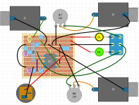
Can you post updated schem of what you have up til now? Just to make sure we are on same page. R2/R3 bias resistors, will work as is, though I tend to go lower as long as a 1M comes from mid point to the non-inv input.
Measure the voltage across the existing cap.Alrighty, i'll try going for a spare 4.7uf cap i have laying around, it's electrolytic however, should the positive end face R2/R3?
So changing the biasing resistors R2/R3 down won't give me any benefit?
Orient the electro to match that voltage.
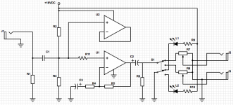
R2/R3 at 2.2 meg and C1 at 0.1uf are fine. You are way under 2Hz rolloff point there. Making the resistors lower will 'make the bass worse', you would to increase C1 to compensate.
C3 at 3.3uf means R4 shouldn't be lower than around 16k. Is that your problem ? C3 needs to be bigger.
C2 depends on whatever is connected after it. 100uf would be a good 'universal' sort of value as you are feeding pots and so on.
C3 at 3.3uf means R4 shouldn't be lower than around 16k. Is that your problem ? C3 needs to be bigger.
C2 depends on whatever is connected after it. 100uf would be a good 'universal' sort of value as you are feeding pots and so on.
R2/R3 at 2.2 meg and C1 at 0.1uf are fine. You are way under 2Hz rolloff point there. Making the resistors lower will 'make the bass worse', you would to increase C1 to compensate.
C3 at 3.3uf means R4 shouldn't be lower than around 16k. Is that your problem ? C3 needs to be bigger.
C2 depends on whatever is connected after it. 100uf would be a good 'universal' sort of value as you are feeding pots and so on.
Perhaps i might want to increase the corner frequency a little. 2hz roll off is too low for instruments, maybe a roll off a 50hz is appropriate . I currently have R4 at 110K and R5 at 470k i believe.
C2 will be connecting to specifically guitar amplifiers. Perhaps it could even be connected to bass amps as well.
If C3 is at 3.3uf, therefore R4 should be 16k as you stated... therefor
If R4 is at 110k, C3 should be at 20uf?
The original booster circuit recommended 10uf, perhaps i'll buy and try both for C3.
I'll got with 100uf for C2, but for curiosity sake i'll go down to 20uf.
Here is an audio example of what the circuit sounds like so far. First example goes as so Guitar > line in with HiZ engaged. Second goes example Guitar > Booster > line in with HiZ engaged.
https://soundcloud.com/asher-gregory/booster-comparison-v21
Last edited:
Yes, C3 now on latest schem is the one to look at with R4, that will compute the roll-off of low end.
I couldn't open your file. For some reason it says IE is an unsupported browser.
You shouldn't guess at any values. Decide on your specification, bandwidth and gain and design accordingly.
You shouldn't guess at any values. Decide on your specification, bandwidth and gain and design accordingly.
C3 > sqrt(2) * C1 * {R2||R3} / R4If C3 is at 3.3uf, therefore R4 should be 16k as you stated... therefor
If R4 is at 110k, C3 should be at 20uf?
The original booster circuit recommended 10uf, perhaps i'll buy and try both for C3.
I'll got with 100uf for C2, but for curiosity sake i'll go down to 20uf.
Here is an audio example of what the circuit sounds like so far. First example goes as so Guitar > line in with HiZ engaged. Second goes example Guitar > Booster > line in with HiZ engaged.
https://soundcloud.com/asher-gregory/booster-comparison-v21
for R2=R3=2M2 & C1=0u1F, R4=10k (less noise than 110k)
C3> 1.4*1M1*0u1F/10k > 15.4uF.
Use 15uF (just about big enough since the root2 is approximate), or 22uF, or 33uF, but reform it slowly (and discharge it) before assembly.
Then you can adjust C1 to a smaller value to see if you prefer a higher roll-off frequency.
Last edited:
I would still prefer that you used the spare 072 to buffer one of the high output impedance TR outputs.
pots are not good line drivers.
pots are not good line drivers.
I go with what Andrew says, and the spare 072 as an output buffer is very simple to implement and useful for driving lower impedances. If you want to monitor and use say a chip amp with 10 or 20kOhm inputs it will drive it well, and not alter the sound based on volume pot position.
- Status
- Not open for further replies.
- Home
- Live Sound
- Instruments and Amps
- TL072 2ch booster