Hey Folks, just need a little hand on designing a 2ch booster Circuit for a bass or guitar. 1 input with two outputs, The idea is that i found a schematic online for a 10db booster using a TL071. I however have a TL072, what i am thinking is that i could insert a simple SPDT to switch between Pins 3 and 5 of the TL072. Then have separate outputs on pins 1 and 7
I am quite naive on creating circuits, so please excuse me. i've made two possible configurations. The first im thinking will probably work but i am unsure. I've simply attempted to duplicate the TL071 schematic.
All component values are the same as the TL071 circuit
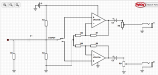
I am quite naive on creating circuits, so please excuse me. i've made two possible configurations. The first im thinking will probably work but i am unsure. I've simply attempted to duplicate the TL071 schematic.
All component values are the same as the TL071 circuit
Attachments
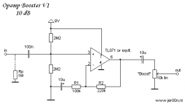

First one is OK electrically.
Second one has a couple of issues. The + input to the opamp not in use must not be floating and the feedback network return needs to be ac coupled to ground.
A TL071/2 is easily capable of feeding two amplifiers from its output. Why not just use circuit #1 and have to pots on the opamp output ?
Practical issues... the low supply voltage will seriously limit the output available. 18 volt would be much better. You could also try the TL061/2 opamps which are low power versions and would greatly improve battery life.
Discard the 3rd diag.
All your opamp are on a single supply. All have AC coupling on input and output. Add DC blocking to the feedback leg.
All will work with a supply upto ~36Vdc. Check the datasheet for absolute maximum supply and recommended maximum supply.
The maximum output is approximately 1/3rd of the supply voltage. 30Vdc allows upto 10Vac.
9Vdc from a battery allows upto 3Vac and with a gain of 3.2 that is clipping with ~900mVac input.
For battery use look for a rail to rail output and look for a very low quiescent current.
If you can afford the weight and the size, use two 9V batteries. That allows upto 6Vac at output (1.8Vac input) at clipping.
You can operate with both channels connected to the Source and then use one, or both, outputs.
The adjustment pot on the output has a variable output impedance. @ -6dB (half voltage) it is highest and really should have a Buffer to drive the output line/cable.
You could use the spare channel of a dual opamp to act as your Buffer. The tlo7x is not particularly good for this, but if you add a 200r direct to the output pin and then take your output from the 200r it should drive lines upto 10m and maybe to 15m
Is any of your gear balanced impedance? Most professional gear and PA gear and stage gear is balanced impedance.
The capacitors are quite low value and the resistors are quite high value. This will be a bit noisier than using resistors sized at 1/10th those values. And you could go even lower for less noise.
Last edited:
According to people who have built the First circuit that it works fine.
My friend wanted two outputs both with booster. If i had a TL071 i would simply build two of the same circuit. I believe my friend has access to a 18v power supply.
Could i perhaps wire in a switch that will simultaneously switch the signal between pins 3 and 5 but also ground pins 3 and 5? eg. When Signal is connected to Pin 3 , pin 5 is automatically connect to ground?
This Piece of gear is specifically to be used to drive a instrument line into separate amplifiers. 🙂 So basically all unbalanced
Maybe I'm not understanding you here...
There is no problem adding a second pot to #1 diagram. That would give you two independently adjustable outputs. If its a requirement that only one output be active at a time then the easiest way is to switch the two pots in and out of circuit.
There is no problem adding a second pot to #1 diagram. That would give you two independently adjustable outputs. If its a requirement that only one output be active at a time then the easiest way is to switch the two pots in and out of circuit.
I could either 1. Use only half of the TL072, which is all i have. Or 2. Perhaps modify the circuit so that one half of the TL072 is a boost and the second half is a buffer. or 3. Use the second half of the opamp to act as a additional boost before the switch.
Ahhhh i see, i forgot to add a capacitor between R4/R5 and R2.
Yes !
I could either 1. Use only half of the TL072, which is all i have. Or 2. Perhaps modify the circuit so that one half of the TL072 is a boost and the second half is a buffer. or 3. Use the second half of the opamp to act as a additional boost before the switch.
There is no problem feeding both opamp + inputs simultaneously from the same source. Also, you could have one opamp (the first stage) as a buffer with a pot at the output and feed the second opamp direct from the first opamp output (before its pot) and configure the second as a stage with gain.
Your welcome 🙂
One further thought... if you really want one section as a buffer and one as a gain stage then I would probably suggest feeding both inputs simultaneously and configuring each stage to have the gain you want. The reason for that is because running on 9 volts means you have little enough headroom as it is, and to feed one stage from the other throws even more of that headroom away.
So configure it as in your second picture (ac coupled feedback) and feed both opamp inputs together. If each feed needs to be switchable then add the switch at the opamp outputs.
Does this work?
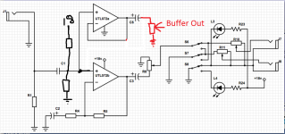
S1 switches out the "extra gain" and feeds the outputs of TL072b from R8 to ground. S6, S7 and S8 are one 3DPDT switch. L3 and L4 are LED's. R10 and R11 are volume pots.
Power Supply Changed to 18v DC for added headroom. What values would R3 and R2 need to be for the IC? Also what values would R23 and R24. L3 is a red LED run @2volts forward voltage 5-10ma and L4 is green with the same values.
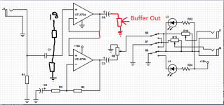
Also. If i wanted TL072b to act as a buffer and the ouput of R9 from TL072a to feed into TL072b, what would i need to change? I would also take out R8 and S1 then connect it to S6
S1 switches out the "extra gain" and feeds the outputs of TL072b from R8 to ground. S6, S7 and S8 are one 3DPDT switch. L3 and L4 are LED's. R10 and R11 are volume pots.
Power Supply Changed to 18v DC for added headroom. What values would R3 and R2 need to be for the IC? Also what values would R23 and R24. L3 is a red LED run @2volts forward voltage 5-10ma and L4 is green with the same values.
Also. If i wanted TL072b to act as a buffer and the ouput of R9 from TL072a to feed into TL072b, what would i need to change? I would also take out R8 and S1 then connect it to S6
Attachments
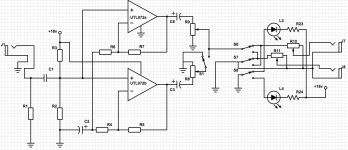
I think (not sure) that C2 needs to be duplicated so that each opamp has it's own NFB back to Signal Ground.
A big C needs to be added across R2 to attenuate hum and interference on the +18Vdc supply.
The high gain/low gain could be a switched resistor across R4, or across R5.
That leaves tl072a spare to act as your Buffer AFTER the vol pot.
It's the vol pot that has a variable output impedance that makes it unsuitable for driving a medium length line. vol pot cannot drive a long line.
The indicator LEDs are back to front. You have them as current blocking diodes. +18V may blow them up, since LEDs don't make good diodes.
I suggest you add some RF filtering to the input.
You could argue that ideally C2 should be duplicated although in practice there is no problem as long as the cap is large enough. Interaction would only occur at low frequency when the caps reactance became significant. Make it 100uf and there is no problem.
I think Andrew has misread the circuit saying to add a big cap across C2 as that would kill the audio. You could however add a cap there and then add separate feed resistors to the opamp inputs but that is all added complexity. R2 and R3 can be high in value to minimise battery drain, say 470k. R23/24 you will have to decide on test. A modern high brightness LED will be blindingly bright at 1ma which is around 15k. An LED from years ago would need nearer 820 ohms and still not be anywhere near as bright. Higher the better for current draw too.
Your switching of the IC output doesn't follow good practice because if the pot is turned up then the opamp sees a 'short' at AC.
A 'buffer' is typically using the opamp with 100% feedback which is easy. R7 becomes a 'short' (a link) and R6 is removed. That gives a voltage gain of 1. If you then feed that opamp into ICB you do that directly and omit the connection from R2/R3 because now the second opamp is already seeing the correct DC present on its inputs.
Edit... I see I've got your buffer the wrong way around. If its opamp B you want as the buffer then link R5 and remove R4
Yes, I mis-read it...........................
I think Andrew has misread the circuit saying to add a big cap across C2 as that would kill the audio. You could however add a cap there and then add separate feed resistors to the opamp inputs but that is all added complexity. R2 and R3 can be high in value to minimise battery drain, say 470k.
It would need an isolating resistor to separate the bias side from the audio side.
the current in most LED specifications is the no damage maximum current if you keep the LED cool enough.R23/24 you will have to decide on test. A modern high brightness LED will be blindingly bright at 1ma which is around 15k. An LED from years ago would need nearer 820 ohms and still not be anywhere near as bright. Higher the better for current draw too.
The normal working current is usually very much lower.
The very first circuit is fine, it can drive 2 output pots and you switch between them easily without clicks or pops.
If you only have dual Op Amps , fine, just use one half, properly unuse/neuter the other by feeding its + input to the bias network, and shorting output to - input, connecting it to nothing else.
Keep it simple 🙂
If you want to add Leds, use a common SPDT footswitch, one half chooses which pot cursor gets connected to output jack, the other which LED gets +9V through a resistor.

There are a couple of problems electrically (which are easily corrected) but the buffer isn't doing anything useful as it stands. You would get the same (better even because you gain a bit of headroom) performance by not using the top opamp as its drawn. It would only be useful if you used the top opamp to feed one of the output pots.
- Status
- Not open for further replies.
- Home
- Live Sound
- Instruments and Amps
- TL072 2ch booster