hi...
this is my first post on this site.. but I couldn't resist putting in my 2 cents on this one.
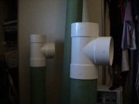
To begin with, have any of you guys actually tried cutting pvc pipe of this dimension? Not as easy as it sounds. I got a bug to make this same design about five years ago... Can't tell you how much PVC I went through while on this quest. I originally wanted to use the corkscrew idea.. I still think it would be a great idea. But much easier said than done. I ended up with many compromises, I basically settled on straight pipes within a pipe. I'll try to attach a picture of them... don't know how well that will work out. Anyway, some details... I ended up using 10 inch high pressure water pipe (the walls are about an inch thick) thinner pipe produced alot of resonance. The speakers are approx. 45 inches tall, and weigh approx. 135 lbs each. The drivers are scanspeak.. I'm pretty happy with the sound, the base is tight and deep, with no bloating. I've never been able to compare them with anything because they are just to hard to move.. should of built in handles.
I had alot of fun making them.. but by the time I was done..I was done..
Good Luck....
steve
this is my first post on this site.. but I couldn't resist putting in my 2 cents on this one.
To begin with, have any of you guys actually tried cutting pvc pipe of this dimension? Not as easy as it sounds. I got a bug to make this same design about five years ago... Can't tell you how much PVC I went through while on this quest. I originally wanted to use the corkscrew idea.. I still think it would be a great idea. But much easier said than done. I ended up with many compromises, I basically settled on straight pipes within a pipe. I'll try to attach a picture of them... don't know how well that will work out. Anyway, some details... I ended up using 10 inch high pressure water pipe (the walls are about an inch thick) thinner pipe produced alot of resonance. The speakers are approx. 45 inches tall, and weigh approx. 135 lbs each. The drivers are scanspeak.. I'm pretty happy with the sound, the base is tight and deep, with no bloating. I've never been able to compare them with anything because they are just to hard to move.. should of built in handles.
I had alot of fun making them.. but by the time I was done..I was done..
Good Luck....
steve
Attachments

Hmmm
Thoughts are coming to mind of moulds and thick paper-mache! It should be a well damped construction method, and I always liked playing with glue at school!🙂
Thoughts are coming to mind of moulds and thick paper-mache! It should be a well damped construction method, and I always liked playing with glue at school!🙂
steve said:hi...
this is my first post on this site.. but I couldn't resist putting in my 2 cents on this one....
....I basically settled on straight pipes within a pipe. I'll try to attach a picture of them... don't know how well that will work out. Anyway, some details... I ended up using 10 inch high pressure water pipe (the walls are about an inch thick) thinner pipe produced alot of resonance. The speakers are approx. 45 inches tall, and weigh approx. 135 lbs each.
steve
A) Welcome to DIYAudio.
B) Thanks for the heads up on resonances using schedule 40 PVC pipe in a Transmission Line Enclosure.
C) I don't think those resonances will be a problem here with this design because the pieces are only 6 inches long, and joined at 45 degree angles. Your pipe-within-a-pipe design-I believe a
French inventor came up with that in the 1920's or so, he has been mentioned on this forum- utilizes pieces that are much longer, therefore have less stiffness. Short pipes, joined at 45 degree angles, are intrinsically more rigid than long pipes just as small wooden boxes are intrinsically more rigid than large boxes.
However, people deciding to use long pieces of PVC pipe in Transmission Line Enclosures now know to beware. 🙂
Hi...
I hope your right about your theory about reduced resonance with the short 45 degree construction, I doubt that resonance will be particularly reduced. The resonance peaks at fairly high frequencies, try tapping a piece of PVC with a hammer sometime.. it practically rings. I used mass to deal with this issue.. but there are certainly other options, the most obvious is to surround your pipes with a non-resonant material..
My other question has to do with constuction techniques.. cutting PVC pipe is really much more difficult than you might imagine. Cutting a straight slice out of a 6 inch pipe with a table saw is practically impossible without a jig, cutting at a 45 degree angle will be even more difficult.
My original plans where to build the speakers in stacked sections, one section for each turn of a spiral. Each section would include both the outer border of the pipe with an integrated spraled flute. Each speaker would then be constructed by stacking one section on top of the next. I
0ops... wasn't quite done when I accidently hit the submit key. I still think the idea of molding these fluted sections would provide considerable construction advantages. Actually, now that I think back on it.. I only thought of the segmented construction technique after I had given up on constructing the spiraled (auger) within a formed pipe, and already had most of the form completed.
I have one more small piece of advise to offer on this project.. PVC speakers are not for the married man.. because unless you really.. and I mean really.. disquise them.. they are going to look like sewer pipes. and unless your wife is much more understanding than mine, she won't be happy with sewer pipes in her living room.. no matter HOW good they sound. Trust me on this one..
have fun...
steve
Hmm...lesse...where did I leave off...(this forum goes too fast...hey everybody, stop posting while I'm gone!! 😛 )
Hmm. Ya don't understand how to cut the spiral into it.
Real easy to show you if you were right here! Damn words...
Well, you cut a 22.5° angle on one end, right? And you do the same on the other end, so it makes a flattened-peak wedge shape, right? Well when you make one cut, you rotate it some - to make an extreme case of 90°, well, geez, I don't know how that could be put into words either. Grr I hate trying to describe totally visual things
Tim
I believe most Transmission Lines are at least lightly stuffed with Dacron or whatever. The higher the resonances, the better, since stuffing is much more effective at suppressing higher frequencies than low. With luck, he should get away with lightly stuffing the Line, I guess.
As Kneadle pointed out, the speakers are going into their on-the-way first child's room. If the stuffing doesn't work that well, at least he won't have to listen to complaints about "undamped mid-frequency resonances smearing the soundstage" until the kid learns to talk in three years or so.
However, he mentioned that he does plan to build another set shortly, as do I. We have had several good suggestions so far, plus mention of flexible aluminum heating duct that looks promising, when combined with other materials.
kelticwizard said:One more thing. Because the taper is only 1:1, what would happen if you made this line longer? I was thinking, maybe you could start with the 6" PVC and then taper this down to a four inch diameter pipe and make the pipe one wavelength long. Wouldn't that give a big boost at bass frequencies?
Any length pipe open at one end and closed at the other is a quarter-wave resonantor. By extending the length of the pipe beyond that supporting a primamry resonance too far from the driver's free air you will decrease the bass.
dave
Sch3mat1c:
Got it covered, Sch3. It is that angle we rotate that I am working on right now.
I think I am going to forsake the part where the base is all on the floor, because there will be few pieces left to make the spiral effect. I am sure Kneadle can build an adequate mount for it.
So far, I am leaning toward 22 degrees, wihich will put the woofer center about 30 inches off the ground.
13 pieces, one of which lays on the ground, leaves 12 pieces of 6 inches each. To raise the bottom to 27" off the ground means that each piece must travel upward at 22 degrees.
How do you think about that?
It has been some years since I was in the 'madness', so I will have to do some digging to see if I still have my notes. But until I come up with my old sketches I will try to explain the idea a little more clearly. My brother in law owned a plastics injection molding company, so my original ideas involved injection molding. Pretty pricey unless your ready to make a bunch of speakers. But the concept would be essentially the same if you where to produce a mold for fiberglass or similar material. Each 'segment' would be constructed to include an external wall, and a single spiraled flute. The outer portion of the external wall could take any shape, circle, oval, rectangle if you chose. It could also have a flat baffle to accept a hole to mount a speaker. The inner portion of the external wall would be circular. internal to the inner wall would be a 360 degree spiral (as in a spiral staircase...without the steps.) This single segment could be cast from a two piece mold.. top to bottom. I've never seen fiberglass cast in a mold.. so I'm not sure if it would be a suitable material.. But I'm sure that there must be some suitable material for poured castings. Ferrocrete comes to mind.. though I'm sure that there are lighter materials available. The height of each segment would be determined by the cross sectional area desired for your port. Each speaker would be constructed by stacking one segment on top of the next untill you reached the desired length of your port. During assembly it would be a simple matter to install dacron or wool. A more ambitious effort might include multiple molds so that you could vary the size of the port from a smaller to larger cross section. Assembly would be quite a simple matter. My 'tube' speakers are mounted on an aluminum plate, and ported to the rear. This segmented speaker could be mounted similarly. The top segment would simply be covered with a flat cover to match the materials of the sement. Whats more.. it could be made to look quite attractive.
food for thought
food for thought
Go away for a couple days and all sorts of interesting stuff pops up 🙂
No discussion of PVC speakers is complete without looking at Rob Sampson's creations.
This one is Baby Snakes... more at the TL-Site.
Rob kills the PVC resonance with his tapering 2x4 -- not applicable here.
And the most widely accepted by female design i ever did was with a piece of 6" PVC.
dave
No discussion of PVC speakers is complete without looking at Rob Sampson's creations.
An externally hosted image should be here but it was not working when we last tested it.
This one is Baby Snakes... more at the TL-Site.
Rob kills the PVC resonance with his tapering 2x4 -- not applicable here.
And the most widely accepted by female design i ever did was with a piece of 6" PVC.
An externally hosted image should be here but it was not working when we last tested it.
dave
Hmm. Yeah, I guess 20° would do it for the rotation.
Could always build a test bed out of 2" PVC to see if it works right!
Tim (hmm, we have some 4" cardboard carpet cores in the basement....)
Could always build a test bed out of 2" PVC to see if it works right!
Tim (hmm, we have some 4" cardboard carpet cores in the basement....)
Oops, gotta modify.
To make the octagon, we have to cut each edge at 22.5 deg. That lops 2.48" off the inside at each edge, which means that the inside of each piece is 1.04 inches long. Since we are going by measurements up the middle, which is an average between 6" and 1.04", that means that each piece counts as 3.5" towards the Line.
So we have to add more segments to reach 58 inches in the Line.
Which means that have to vary the angle of the segments , otherwise the Line will be too high-we want the woofer around 30 or 32" high.
At 3.5" added toward the line, we need over 16 segments.
Not so simple. If we want this spiral to have the same outside measurements as the octagon on the floor, the segments in the spiral have to be longer than the segments on the floor. We want to make this "spiral" so that when we look down on it from directly above, it looks like an octagon.
This is nothing that a little trigonometry and a handheld scientific calculator cannot solve. But not tonight. Tomorrow, yes.
Actually, to maintain the same shape as viewed from above, the pieces in spiral, sloping upward at 22 degrees, have to be 12% longer than 6 inches on the outside measurement. That is 6.72" per piece, or an additional .72 inches. If we lengthen the pieces in the spiral-there are 10 of them-by .72 inches, then we have added 7.2" to the Line.
We will have knock about 2 pieces off the Line, bring us to 14 segments, and rejigger the angle of rise slightly to have the center of the woofer around 30 or 32" off the ground. Which means that we will have to rejigger the length slightly, but we will get it close.
We are getting there. Have the figures tomorrow.
You know,
I WAS going to start cutting these things today, but there are too many variables still at stake, it seems. I have to work all day, too.
The "prototype" is a great idea. I think I'll run and get a few feet of smaller pvc to make a model. At least I'll have an idea, then, what might cause difficulty in construction.
Stay tuned!
Dave
PS--the wife is ok with it as long as I paint it in baby motifs. It might make a great baby visual, you know, with all those shapes and colors and things.
PPS--And I have a mount in mind. Proceed with your measurements, by your leave.
Sch3mat1c said:Hmm...lesse...where did I leave off...(this forum goes too fast...hey everybody, stop posting while I'm gone!! 😛 )
Hmm. Ya don't understand how to cut the spiral into it.
Real easy to show you if you were right here! Damn words...
Well, you cut a 22.5° angle on one end, right? And you do the same on the other end, so it makes a flattened-peak wedge shape, right? Well when you make one cut, you rotate it some - to make an extreme case of 90°, well, geez, I don't know how that could be put into words either. Grr I hate trying to describe totally visual things
Tim
I thought of this, but as Kelticwizard shows, it adds a little bit of trigonometry into the design. And like I said before, I'm a linguist. I don't even remember what a cosine is, much less a function of one. Would that I could have bent these things having heated them! Fie!
My paperwork (yes, I'm keeping a log of all my work and all the contacts made) specifically recognizes Rob Sampson and that nautilus design that Planet10 posted a while back. I just "unwound" the nautilus in my brain so that I could build it with PVC. Those two people are first in a (now) long list of acknowledgments. I can barely take credit for my own work , now, but I'm sure it will be worth it.
Dave
ok i can't help but be sucked into the vortex of this geometry problem. i'm an architect and i draw 3d models all the time, so i HAVE to draw this before i have an aneurism thinking about it.
but i still don't know a couple things:
1. is 6" dia. the interior or exterior of the pipe? 3/8" wall thickness, right?
2. is the goal to minimize length? i.e. does the base need to be part of the speaker volume, or could/would you seal it off to maximize the visual spiral 'effect'?
3. is the '1.5 turns' requirement arbitrary? you could get more turns (using more/smaller pieces, of course) in a smaller radius, if you wanted.
/andrew - drinking coffee to prevent brain clottage
Welcome aboard. I knew this would evoke interest, but never to this extent! I'm pleased that other people have so kindly offered their help in the construction of this project.
1) 6" is the inner diameter (ID). 3/8" is the wall thickness.
2) The length is determined by Martin King's mathcad worksheets concerning Transmission Line speakers. This length/stuffing ratio is the closest to an ideal TL I could get for these particular drivers.
3) I have 12' of 6" pipe from which I have to squeeze 60" of enclosure. I thought I could bend it by heating it, but it proved impossible for me. This is what I have. It's not a random number, per se. There is also the component of the actual work involved, so I want to keep it relatively simple (ha hah ah hahah). Fewer pieces is a good thing, at this point.
It's important for me to get this project right for the sake of the NEXT project.
Dave
grind an extra tablespoon of beans for your brain food.
OT congrats
PS - congratulations on your impending family addition. we just had our first 7 months ago.
PS - congratulations on your impending family addition. we just had our first 7 months ago.
- Status
- Not open for further replies.
- Home
- Loudspeakers
- Multi-Way
- TL Design I can't build