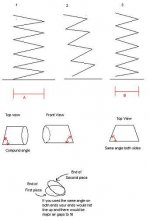
There are potential problems with cutting the pieces like that
When you cut pipe at an angle, the mating surface is now an oval instead of a circle, and when you go to put to two pieces together and then rotate the one to get your pitch for the spiral, it would leave you with an air gap.
Another problem would be that when you started to build and glue the pieces together it would start to slant and the diameter of the spiral would change. As in picture 2. This would be pretty hard to compenstae for.
The way you would need to cut the pipe would be to cut your first angle, flip the pipe around to cut the other end and then rotater the pipe to create a compound angle.
It would be pretty tricky but you would definatly need to make a jig, due to the large number of identical pieces required, and the tolerances they must be held to, to make sure the spiral is air tight.
I will try and draw up some plans for you when i get my cad up and running, Its driving me nuts without it.
Ms paint isn't too user friendly when it comes to trying to represent something in 3d but i gave it my best shot
Attachments
I will try and get the meaurements some time within the week but no promises.
What kind of drivers did you calculate this for? Cause i wouldn't mind building a pair now.
Are those your final meaurements for the spiral in your diagram, If so, what is the desired volume, length of the whole thing unwound, or the height and pitch of the spiral. I will need at least a couple of those measurements to get started.
It would need to be your final measurement because changing one would change all of the angles
Do you want the spiral as compact as posibble or do you want kind of a floorstanding design?
Attachments
Gosh. A few things:
1) The drivers are Vifa P17WG00-06's, constructed by Madisound to crossover to Vifa D27TG05-06's. The design calls for the tweeter to be mounted externally on the tee with the driver, which creates an environment suited for phase displacement work.
2) I have about 12 feet of 6" diameter sewer-grade PVC pipe. Using MJK's worksheets, a 66" pipe is what I wanted to construct. NB: This is not ideal! A 1:1 Sd chokes the bass response. However, it is still quite good, just not as good as a TL could be with this driver. I also have two Tees on which to mount the drivers. They are 12.5" long, with 3" mounts, and I would seal one end of each with 1" wood on the inside diameter. The driver mounts 3" from the pipe itself and extends almost flush to the pipe.
You'll notice in the initial graph I posted that I drew what a 3:1 or 2:1 Sd would look like. However, PVC pipe larger than 6" diameter gets real expensive, and back when I thought I could bend 6" pipe, I still doubted I could bend larger pipe, even if I could find it.
3) PVC goop, I thought, dries rather quickly. Correct me if I'm wrong.
4) Even so, 1-inch pieces might be overkill. Larger pieces might be effective, considering time and cost.
5) A jig or 2 or3 would make things very easy. Keep in mind this builds TWO speaker enclosures. If every piece is identical, or if there are only 2 or 3 different shapes, it could go pretty quickly, with a matching piece for the 2nd speaker always coming into being simultaneously.
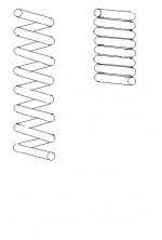
6) We've got to solve the "spiral" aspect, yet. It appears that a very tight one (the one you pictured on the right) is the easiest one, eh? I dunno about that. It really only has to go around once and half again. That's 540 degrees, so that it definitely goes around and down, then ports forward.
7) Get that CAD program going! 😉 Don't worry, this is a weekend-only project. I might take some time otherwise, but the bulk of it is Saturday and Sunday afternoon.
8) I've named the design "The Seraphim."
There. That should do it.
Dave
1) The drivers are Vifa P17WG00-06's, constructed by Madisound to crossover to Vifa D27TG05-06's. The design calls for the tweeter to be mounted externally on the tee with the driver, which creates an environment suited for phase displacement work.
2) I have about 12 feet of 6" diameter sewer-grade PVC pipe. Using MJK's worksheets, a 66" pipe is what I wanted to construct. NB: This is not ideal! A 1:1 Sd chokes the bass response. However, it is still quite good, just not as good as a TL could be with this driver. I also have two Tees on which to mount the drivers. They are 12.5" long, with 3" mounts, and I would seal one end of each with 1" wood on the inside diameter. The driver mounts 3" from the pipe itself and extends almost flush to the pipe.
You'll notice in the initial graph I posted that I drew what a 3:1 or 2:1 Sd would look like. However, PVC pipe larger than 6" diameter gets real expensive, and back when I thought I could bend 6" pipe, I still doubted I could bend larger pipe, even if I could find it.
3) PVC goop, I thought, dries rather quickly. Correct me if I'm wrong.
4) Even so, 1-inch pieces might be overkill. Larger pieces might be effective, considering time and cost.
5) A jig or 2 or3 would make things very easy. Keep in mind this builds TWO speaker enclosures. If every piece is identical, or if there are only 2 or 3 different shapes, it could go pretty quickly, with a matching piece for the 2nd speaker always coming into being simultaneously.
6) We've got to solve the "spiral" aspect, yet. It appears that a very tight one (the one you pictured on the right) is the easiest one, eh? I dunno about that. It really only has to go around once and half again. That's 540 degrees, so that it definitely goes around and down, then ports forward.
7) Get that CAD program going! 😉 Don't worry, this is a weekend-only project. I might take some time otherwise, but the bulk of it is Saturday and Sunday afternoon.
8) I've named the design "The Seraphim."
There. That should do it.
Dave
Looking at the spiral drawings, the corrugated Alu vent ducts we have in Norway should be perfect for this job !
A 1m length can be stretched to appx 3 m and folds in perfect circles. We can buy it in 4,5,6 and 8" dia. with acccessory joints...
It is stiff and extremely light weight, but I feel it should be coated, even if I don't think it will leak air. Surely you must have this stuff in the US ???
The clothes dryer ducts here are mostly are steel wire with soft PVC coating.
Yeah, that's right. When you rotate the joints, you'll get an offset. With thin-wall tubing, this could be a problem with anything more than 1" segments.
I suggest again drawing the lines on the pipe, but all the way around, like, one every 10 degrees or whatever is needed. Keep track of which one is up, of course (a tedious paper record would be helpful), and you should be alright.
This way, when you cut the segment, it automatically has the correct rotation angle built in.
BTW, may I recommend an octagonal shape? 22.5° each end of the pipe, and about 6" long at the long side should do it. You'd only have 13 segments?
Damnit, this project is too interesting...wish I had some 6" PVC!! 🙂
🙂
Tim
I suggest again drawing the lines on the pipe, but all the way around, like, one every 10 degrees or whatever is needed. Keep track of which one is up, of course (a tedious paper record would be helpful), and you should be alright.
This way, when you cut the segment, it automatically has the correct rotation angle built in.
BTW, may I recommend an octagonal shape? 22.5° each end of the pipe, and about 6" long at the long side should do it. You'd only have 13 segments?
Damnit, this project is too interesting...wish I had some 6" PVC!!
🙂Tim
Sch3mat1c said:
I suggest again drawing the lines on the pipe, but all the way around, like, one every 10 degrees or whatever is needed. Keep track of which one is up, of course (a tedious paper record would be helpful), and you should be alright.
This way, when you cut the segment, it automatically has the correct rotation angle built in.
BTW, may I recommend an octagonal shape? 22.5° each end of the pipe, and about 6" long at the long side should do it. You'd only have 13 segments?
Damnit, this project is too interesting...wish I had some 6" PVC!!
Tim
Would you mind explaining that a second time? That way I can be sure I read you right. The first two paragraphs quotes, especially. It sounds like a good idea, but I'm not quite sure I get it.
An octagonal shape might fulfill the expectations, considering that this is experimental.
Thanks,
Dave
Just put a lengthwise line every n° around the pipe.
[Geometry]
Like...a circle...put a polygon inside it, where the verticies intersect the circle put a line down the pipe (like the circle is end-on of the pipe).
[/Geometry]
Then you use that 3 1/8" tall board to line up the pipe when cutting.
To get maximum use of the pipe, you can cut two segments with two cuts, this requires a 180° rotation of the pipe of course, so the cuts form an isosceles (whoops maybe I shouldn't have ended the geometry tag up there 😉 ) trapezoid.
But since we want a rotational offset on those two cuts, you'll want to rotate (for instance) 10° less, i.e. 170°, each cut.
The lines on the pipe are only for convienience, so you just line up the right line and pop out another segment.
- Experimental or not, an octagonal shape might work anyway...just think...maybe, polished or brushed aluminum finish, get a nice space-age appearance going. Don't think octagonal, think curved facets...
Tim
You know, I'm linguist by trade. Math and geometry is so hard for me to visualize. Can you draw a picture of what you're desribing? The "lines" thing inside the geometry brackets has me completely at a loss.
I mean, I can tell that it's the real deal, but I can't make it work in the picture part of my imagination.
Thanks,
Dave
I mean, I can tell that it's the real deal, but I can't make it work in the picture part of my imagination.
Thanks,
Dave
Be glad to give you the angles for larger segments. How big did you have in mind? Two inches, three inches? Say the word and the calculations will be forthcoming shortly.
Now, about the spiral. I assume that you are going to paint this thing and display it as a sort of speaker sculpture-you aren't going to hide this spiral inside a box, are you?
Assuming you are going display this spiral, I have a suggestion. Instead of a spiral all the way around, why not have the bottom of the spiral be a circle that goes two thirds or three quarters of the way around then starts upward in a spiral? This way, the PVC pipe can rest on the floor, and you won't need a stand to support this structure-though I suspect that you probably will want to knock off a nice base for it to rest on, anyway.
Or else you could construct some kind of stand to support the pipe. Anyway, just tell me how many inches, if any, you want to lay on the floor before this thing starts spiralling upward.
Hard to judge the length of the Transmission Line with this thing, because the Inside Diameter is going to be less than the Outside Diameter. I do remember reading about folded Transmission Lines-the kind inside a box-the length is considered the what the length of the middle of the line is. So we will use that idea.
One more thing. Because the taper is only 1:1, what would happen if you made this line longer? I was thinking, maybe you could start with the 6" PVC and then taper this down to a four inch diameter pipe and make the pipe one wavelength long. Wouldn't that give a big boost at bass frequencies?
Okay, it would be a 264" pipe-22 feet-but if you keep spiralling it around, one layer layer lying atop another-you might be able to build a piple of reasonable size.
I have also heard of a 5/8 length tube behind the woofer.
The above are just specualtions. I am imagining that the longer the pipe, the smaller the diameter of the pipe must be. Just a guess.
Anyhow, just let me know the length of the segments you want cut-one, two , three or more inches-and I'll get that info to you.
Another crazy idea....
Make a TL enclosure from a sonotube that has an internal line that looks like a corkscrew.
It would require another smaller diameter tube as the center "leg". For the "screw", make semicircular "C" shaped cutouts from maybe 1/2" MDF. Glue alternating edges together while stacking the circles. When pulled on, it would form a screw shape that would then have to be fixed to the tubes. With this approach, if doable, you could taper the line however you wanted.
Must be something in the air, huh?
Pete
First, Kelticwizard, thanks for the kick in the pants late last night. I am really gung-ho about this thing, now. I was pretty down about it last night. I had experienced three weeks of utter failure implementing the thing. Now it's a near done-deal!
Second, this has a specific application for the baby's room. It's going to be painted in a baby motif, with balloons, and clouds, and moons and suns...and cows, too.
I have no input on the matter.
However, I already had TWO designs handy. After I do this one (which seems very do-able, thanks to everybody's help), I'm going to unleash a variation of the one I've described here. I mentioned earlier that I named them "The Seraphim." I did that on purpose. I have a push-push spiral TL design waiting to spill out onto paper and mathcad, and it will truly capture what I had in my brain.
That's why I keep calling this one "experimental." Not that it's no good, but that with its success, I can move on to greater things!
Third, the original design, not shown, actually was going to employ the idea that the lower part of the spiral would serve as the stand, as you described, Kelticwizard.
Sch3mat1c, I must thank you for your helpful input, and I'd really like to see your idea of an octagonal diagonal calculated. That seems the most feasible, sort of "work/realization" goal.
Another post just came in. Going to check it out.
Thanks
Dave
Pete Mazz said:Another crazy idea....
Make a TL enclosure from a sonotube that has an internal line that looks like a corkscrew.
It would require another smaller diameter tube as the center "leg". For the "screw", make semicircular "C" shaped cutouts from maybe 1/2" MDF. Glue alternating edges together while stacking the circles. When pulled on, it would form a screw shape that would then have to be fixed to the tubes. With this approach, if doable, you could taper the line however you wanted.
Must be something in the air, huh?
Pete
It's been done, believe it or not. I stumbled upon something precisely as you described here: http://www3.ocn.ne.jp/~hanbei/eng-inside.html
I nearly blew a gasket when I googled for "spiral shaped enclosure" AFTER I spent hours dreaming up my Seraphim. But this design is radically different from mine.
Dave
I've enjoyed mentally building spirals all day long. Some thoughts:
It would have to be 6" sched. 40 (with a wall thickness of nearly 1/4 in., in order to saw a compound mitre and leave a surface ready to butt glue. Is that what we are talking about?
Consider that the saw will have to have a 14" or larger blade to make this cut, and THAT is not common.
SY had a very usable approach in his suggestion... relating to the lost wax process. For instance, imagine a toy balloon that is used to make (fun) shapes by twisting and bending it, this could be splattered with plaster to give it some strength and rigidity and then covered with a thicker, stronger layer of plaster or fiberglass for permanence
This balloon may not be something you could buy off the shelf somewhere, but it is something very makeable with polyethylene. Also it could be made in the optimum tapered shape, kept inflated with a small computer-type fan, and pinched to shorten it along the center axis to form a spiraling tube. And why not put it in a box for the regular asthetics and finishing?
Another idea concerning the above mentioned, spiraling auger-in-a-tube plan, is that this auger can be constructed of stacked wood strips with holes drilled at their centers and held together with a threaded rod. This would provide both adjustments for tweeking, or driver changes and TWO parallel spiraling chambers and might lend itself to a push-push driver arrangememt.
Could this be worthwhile?
x. onasis said:
Could this be worthwhile?
Yes. But I have loads of PVC that had better become a couple of speakers--and quick--or else!

Dave
OK, let's build this baby
Let's build it like this (pipe wall is 3/8 inch):
1) The first 180 degree turn (from bottom up) will be a true half circle, in order to provide a solid base.
2) The next 360 degree turn will be a full circle, but spiraling up from the half circle. Let's leave a 6" space between the outer diameter, a slow spiral upward, not very tight at all.
3) The total pipe length should be 66 inches. 8.5" are in the Tee. We need to design pieces that will equal an internal length of around 58 inches (I don't think a half inch will do it).
4) The octagon is the best idea with regard to time and effort. That would translate roughly into 13 6-inch pieces per enclosure. I think.
If Kelticwizard and Sch3mat1c are still willing to do the math/geometry parts, I'd appreciate it. I'll do my own calculations and measure them against yours. This is my only fear: that I'll totally flub the measurements.
To everyone else, many thanks for your suggestions. There is another spiral project in hand after this one is done, and Iwill certainly use some of your ideas.
Both projects are going to be beautiful; I just know it!
Thanks,
Dave
Hmm, another idea to waste your pipe...
Make some flat-sitting segments and glue them together to form smooth, gradual 90° bends...attach these to some straight lengths of pipe, such that you get a U shape. I'm thinking something that sits in front or behind the couch/computer/audio corner. 🙂
Tim
Make some flat-sitting segments and glue them together to form smooth, gradual 90° bends...attach these to some straight lengths of pipe, such that you get a U shape. I'm thinking something that sits in front or behind the couch/computer/audio corner. 🙂
Tim
First of all, this is a very cool idea with some very good looking speakers as an end result. I've been playing around with similiar ideas in my head for quite some time.
Would you have access to a bandsaw?
Finding the aforementioned 14" circular blade saw may be a bit difficult and certainly a fairly dangerous procedure to perform.
A good bandsaw with possibly a cross-slide (is that what they are called?) would probably be the best option for cutting the sections.
Would you have access to a bandsaw?
Finding the aforementioned 14" circular blade saw may be a bit difficult and certainly a fairly dangerous procedure to perform.
A good bandsaw with possibly a cross-slide (is that what they are called?) would probably be the best option for cutting the sections.
A) Your base will only be half a circle? Won't that be ready to tip over? It takes more than thaolf the wieght supported to make a structure stable, even if the half with the woofer is on the supported side.
B) How high do you want the Tee? Your drawing shows 18" X 3 = 54". Most tweeters are 32" or so off the ground-the ear height of the seated person. Is this carefully designed to be crib height, LOL, or a random number?
C) How is the line going to meet the Tee? If it comes from the side, as in Fig. 1, then the line stays nice and smooth, with gentle angles. However, you will have to build mirror pairs. If the Tee is in the middle, as Fig 2 clumsily shows, then there will be sharp angles coming from it to meet the rest of the line. Which way are you going to go?
D) Your quote: "We need to design pieces that will equal an internal length of around 58 inches (I don't think a half inch will do it). The line will be shorter along the inward side of the pipe than the outside. Unless Martin King or someone told you to go by inward length, I will be going by estimated length down the middle. A book I read said to do it that way. If you insist that I count the internal length as the line length, then I will do so. but I am inclined, in the absence of counterbalancing authority, to count the middle as the line length.
Let me know these answers, and I can give you angles.
Attachments
Tuukka, thanks for the heads up. I'll try different ways so I don't kill myself.
Kelticwizard,
A) Ok, let's make the base more than a half circle. It appears that the bottom should be the full circle, with the spiral part only a half circle. Again, I'm so glad I found this forum.
B) It's a random number. Crib height....that's a good one. The answer to part C will affect this, too. The 18"x3=54" is a "guesstimate" that didn't take into account the mounts of the Tee and the sealing of the Tee. In fact, upon double-checking, we should cut 60" of pipe, not 58". Doggonit. That brings up a question. See the end of this post.
C) I think mirror pairs, as shown in fig 1, is the way to go. An important note here is that the last piece, the piece on which the tee will mount, should be at--oh no--I can't remember the angle! The front baffle of an equilateral tetrahedron would be tilted at what angle? (see pic) I can't find where I wrote it down! Should I just fire the driver horizontally?
D) I meant "right down the middle" instead of one side or another. We are bending 60" of pipe into a spiral.
QUESTION on B: The Tee can mount either one of two ways. One way the driver fires directly down the pipe. That's the way the measurements currently assume. The other way is like a periscope, which would resemble a "normal" ML TQWT. Which way would be better?!?
Thanks,
Dave
PS--I still haven't understood how to make the circle into a spiral.
Attachments
- Status
- Not open for further replies.
- Home
- Loudspeakers
- Multi-Way
- TL Design I can't build