I have 2 model 1`s, a first and second generation with AUX input. They both suffer from the notorious tuning capacitor failure were it`s nearly impossible to tune in a station due to the large amount of noise while tuning in.
I decided to purchase a couple of replacement Varicon capacitors from an Ebay vendor that claimed they are original Tivoli parts.
Varicon capacitor for Tivoli Audio Polyvaricon | eBay
Anywho, I finally got to installing them but there are some issues. The good news is that the crackling and noise are gone but now, the frequencies displayed on the dial are waaaayyyy off.
Actual 107 FM shows up near 97. Dialing the Tivoli down, it will tune in actual 105 FM at around 95.
Tuning down below 95 doesn't seem to catch anything. Tuning the Model 1 up to 98 brings in actual 88!
Going further up to 106, actual 93.5 FM is tuned in. At the very top of the dial, actual FM96 is tuned in.
AM stations fared a little better though, actual 690 was only off by a bit.
Both radios have approximately the same issues.
When replacing the Varicon, I was very careful to install the new ones in the same orientation as the old ones. Now, I suppose it`s possible that the new Varicons may not have been ID`d properly that is to say, the clear plastic covers can be oriented 180 degrees relative to the tuning capacitor assembly.
Assuming that the correct part was properly installed, could this be an alignment problem? I considered rotating the entire varicon assembly 180 degrees but I thought the prudent thing to do was to ask here before tearing into the disassembly once more which is a PITA.
Never ever liked that type of variable capacitor went through many in old small SS receivers .
First ---I take it the old one and the new one are exactly the same value of capacitance SWING ?
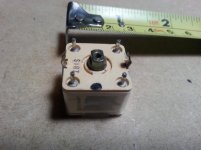
Second -- there should be two( at least ) small slotted semi-variable adjusters on the top of it --did the old one have those ?
These "tune in " the correct capacitance for the amount of travel .
If not there must be adjustable ( semi-variable ) small capacitors near it , correct tuning requires adjustment at BOTH frequency extremes .
First ---I take it the old one and the new one are exactly the same value of capacitance SWING ?
Second -- there should be two( at least ) small slotted semi-variable adjusters on the top of it --did the old one have those ?
These "tune in " the correct capacitance for the amount of travel .
If not there must be adjustable ( semi-variable ) small capacitors near it , correct tuning requires adjustment at BOTH frequency extremes .
Duncan, take a look at the PCB with new Varicon installed. There are a fair amount of adjustments possible.
As for the capacitance specs, I cannot answer that question. I just assumed that the only variable part of the capacitor was via the tuning knob itself.
As for the capacitance specs, I cannot answer that question. I just assumed that the only variable part of the capacitor was via the tuning knob itself.
Attachments
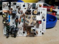
The 4 screw heads on top of the tuning capacitor are trim adjustments, which must be made for
the frequencies to line up with the dial. You'll have to get the procedure document somewhere.
Do not, repeat, do not touch anything on the pcb itself, only those on the top of the tuning capacitor.
These new parts do not come pre-aligned, since the adjustment is different for each radio into which
the new part is installed.
Last edited:
Fear not, I wouldnt touch anything. I compared 3 varicons side by side by side and sure enough, they are all in different positions.
Now the big question is, where to get the alignment procedures?
Of all the research I did prior to actually attempting this repair, nowhere was this ever brought up.
I`m $75 into this project and further behind then when I began🙁
Now the big question is, where to get the alignment procedures?
Of all the research I did prior to actually attempting this repair, nowhere was this ever brought up.
I`m $75 into this project and further behind then when I began🙁
Attachments

Some kind soul may offer the factory's alignment procedure here. Or you could try to
find out empirically how to do it.
find out empirically how to do it.
I cannot find a link to take you to a website that will display a method of adjusting this type of obsolete tuning capacitor .
While prolific in small transistor portable radios of the late 50,s /60,s they were replaced by tuning diodes /varactors and then chips .
This leaves doing it the "manual " simple way ,especially if you have no RF signal generator, you might find it annoyingly long winded in this "instant action " age but it will work --eventually and you have to be really slow at it --one step at a time .
Are you still interested or have you found a website I missed that tells you how ?
Thanks for the replies Duncan, Reyma.
It`s unfortunate that I arrived at this stumbling block after purchasing and installing these replacement parts. Before attempting any kind of repair or mod, I research it extensively and then decide whether or not to tackle it.
This is clearly beyond my capabilities both in concept and the necessary tools that are needed, I never would have attempted doing them in the first place had I known what was involved.
I emailed the Ebay seller of the varicons and Tivoli regarding the alignment procedure but did not receive a reply from either. Luckily I kept the old parts and reinstalled them in their respective radio`s because were essentially useless without being re tuned.
The older non-auxiliary radio works better than it did after a cleaning of the selector switch and volume pot, there was no change in the newer one after reassembly.
If I ever come across any useful information, I`ll revisit this post.
Why not take him through it Rayma ?
Don't have the procedure for adjustments, but I'd first find out which two are FM by slight adjustments.
Then which of the pair is the high end or low end. Mine is still in working shape, or I'd give it a go.
Right so far Rayma but it looks like Michael has given up ?
A fault that does not require any tuning adjustment I have come across is that at the low frequency position ( either a RF signal generator or strong station ) and at the high frequency side ( end ) check if BOTH are equally off by the same distance --if so just move the pointer --its as simple as that !
Otherwise we are back to tuning it ( oscillator tuning adjustment ).
Last edited:
As this is a contact problem I suggest to apply some spray to the axis. And yes these Tivolis are the meanest crap I ever touched.
Not entirely, I just reassembled in order to have 2 sorta working radios again.
It`s just a matter of time before they become unusable, at least Ill have the replacement parts on hand.
It`s just a matter of time before they become unusable, at least Ill have the replacement parts on hand.
As this is a contact problem I suggest to apply some spray to the axis. And yes these Tivolis are the meanest crap I ever touched.
Are they not air dielectric capacitors?
NEVER --EVER --and I mean it !! spray inside one of those type's of variable capacitors.
The inserts develop a COATING that changes the capacitance swing making it much worse or impossible to tune correctly ---
You have been WARNED !!
The inserts develop a COATING that changes the capacitance swing making it much worse or impossible to tune correctly ---
You have been WARNED !!
no, there is some poly-whatever plastic-film. Air dielectric varicaps were orders of magnitude biggerAre they not air dielectric capacitors?
Last edited:
Polyethylene. It has good HF properties, and a relative permittivity over 2.
I believe the problem with these tuning capacitors is the sliding pressure contact with the rotor.
If this is properly cleaned it should work like new, and no adjustments should be necessary.
If someone has a bad one, look for the sliding ground contact to the shaft. Sometimes it is
located at the back end of the shaft, and sometimes on the side of the shaft in the front.
https://www.nonstopsystems.com/radio/img-ant/antenna-magloop-air-varicaps-B.jpg
Last edited:
- Home
- Source & Line
- Analogue Source
- Tivoli Model 1 issues