Electronics is both a profession and a hobby for me but I haven't focused on music electronics for a long time. Now I want to make a guitar combo for my son as a lockdown project and will appreciate some tips.
The idea is to make a combo that can be used as a standalone when he wants to play without an external effects unit. So it will include these -
- Gain
- Overdrive
- 3-band equalizer
- Reverb
First question: What sensitivity should I aim for to drive the amp to full power with the gain and volume controls maxed out on the clean channel with tone controls in the flat position? 10mV, higher, lower? (My son's main guitar is an unmodified Washburn N2 but he plays other models too).
If I understand right your question is how much voltage to expect from guitar pickups. It depends heavily on the type of pickup, but for the relatively hot humbuckers in that Washburn, you might find normal strumming peaks somewhere around 400mV, and really hitting it hard might reach peaks of 1.2V. Give or take 50% on each guess, because it really can vary a lot. For comparison, normal strumming on my Telecaster single-coil pickups peaks around 150mV.
Last edited:
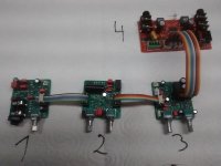
I have built my guitar amps from scratch for a lifetime going the solid state route. This includes circuit design, populating pcbs (SMD mixed with THT parts) and verifying. So I created several modules:
1. input gain stage with overdrive. Switchable "hot" channel for very high distortion (PCB 5x5cm)
2. Reverb/Chorus based on FV-1 chip from Steve Barr. (PCB 5x5cm)
3. Master channel with 1-knob tone control and soft limiter (PCB 5x5cm)
4. Power module based on TPA3118 from TI. Suitable for ca 8/25W into 8Ohms at 12/24V power supply.
Power supply may be any notebook power adapter, a 12V-SLA, 12V-car cigarrette lighter jack etc. ppp.
If you are comfortable with SMD soldering I could send you some bare pcbs.
You will find some useful circuits on ESP homepage.
Attachments
Thanks for the reply but that's not quite what I'm looking for. To give an example: Microphones have a wide range of output levels depending on the type, model and the SPL impinging on it. Standalone PA amps and many mixers have a sensitivity of around 1mV to produce a line level output. Some go as low as 0.3mV but that may be overkill for many applications and make maintaining a good SNR difficult.If I understand right your question is how much voltage to expect from guitar pickups. It depends heavily on the type of pickup, but for the relatively hot humbuckers in that Washburn, you might find normal strumming peaks somewhere around 400mV, and really hitting it hard might reach peaks of 1.2V. Give or take 50% on each guess, because it really can vary a lot. For comparison, normal strumming on my Telecaster single-coil pickups peaks around 150mV.
Guitar pickups by themselves may have a smaller range of output levels than microphones. But OTOH they have at least one level control - often more if external effects units are used - before the signal reaches the amplifier. These controls are normally not turned up to full. Yet the input signal to the amp must still be strong enough, not only to drive the amp to full power but also to make use of any built-in overdrive circuit.
All of these factors have to be considered when deciding on the maximum sensitivity. It's easy to make an amp highly sensitive but hum and noise must also be considered, especially without a noise gate.
So the question remains: What would be a good sensitivity level for a standalone guitar combo, roughly corresponding to 1mV for a microphone amplifier?
You will be fine with 20~50mV input for full output, i.e. a total voltage gain in the ballpark of 500V/V. More gain for extreme distortion - raises any noise as well.
Hi,
Should be a fun project. I'm planning a similar lockdown build myself.
Are you building a solid state amp, or a valve amp?
Should be a fun project. I'm planning a similar lockdown build myself.
Are you building a solid state amp, or a valve amp?
Thanks, that gives me a starting point.You will be fine with 20~50mV input for full output, i.e. a total voltage gain in the ballpark of 500V/V. More gain for extreme distortion - raises any noise as well.
And thanks also for your offer of your PCBs. It's very generous of you. But I live in a very remote place and with the country in full lockdown, not even the postal service is functioning. I'm designing everything from the individual component level.
It has to be solid-state. I cut my electronic teeth on valves and I would love to work with them again, but I don't have any with me now.Hi,
Should be a fun project. I'm planning a similar lockdown build myself.
Are you building a solid state amp, or a valve amp?
I live in a remote corner of a developing country where mail order never took off. Even in the internet age, it's still not easy to buy electronic parts online. I've come to rely more and more on AliExpress in recent years.
Last edited:
Thanks for the reply but that's not quite what I'm looking for.
Thanks for clarifying! Now I'm reading and learning about the concept of input sensitivity. I guess I'm pretty clearly not qualified to answer this question, but FWIW, I've googled up numbers on some classic amps that all seem to have "high" inputs at 10-15mV and "low" inputs at 20-30mV.
It is a good idea to simulate your design with LTSpice. This can be very helpful specially with discrete designs.
Start your design with the choice of power supply and power amp. If you want to build really from scratch, class AB is the way to go. I recommend the schematics found at ESP being a trustworthy alternative to all the BS you will find on the internet. Combined with a (toroidal) power transformer, rectifiers and bulk caps you are done with the power section. I you prefer a smarter solution buy a readily built class-d-amp-modul based on TPA3116/TPA3118 and feed it with some ac-notebook adapter from the stash. And if you want to power with batteries, class-d is your only choice.
It has to be solid-state. I cut my electronic teeth on valves and I would love to work with them again, but I don't have any with me now.
I live in a remote corner of a developing country where mail order never took off. Even in the internet age, it's still not easy to buy electronic parts online. I've come to rely more and more on AliExpress in recent years.
A real shame you can't lay your hands on some lovely glowing valves, but a solid state project should be just as much fun.
What I know about solid state technology could be written on the back of a thing very small, so I'll leave you in the hands of those here who know what they're talking bout.
Good luck with the project, and stay safe.
The Fender Deluxe AB763 circuit (arguably the finest of Leo's designs) was built with an intended source level of ~40 mV.
Thanks. That corroborates well with what others have contributed.The Fender Deluxe AB763 circuit (arguably the finest of Leo's designs) was built with an intended source level of ~40 mV.
I didn't want to rely solely on my own measurement of one or two guitars. Besides, the chain of level controls that are usually inserted between pickup and amp input further complicates the issue, unlike the case of a mic mixer/amp where the mic is plugged directly into the preamp input.
As far as the question of input sensitivity is concerned, whether the technology is solid-state or thermionic is irrelevant.so what's solid state in an AB763?
What type of music does he like/play? That is an important thing to determine. Also what is the power level are looking at?
You mentioned noise earlier, so do keep in mind, the volume control potentiometer inside the guitar becomes the dominant source of Johnson-Nyquist noise if turned down from full volume!...the chain of level controls that are usually inserted between pickup and amp input further complicates the issue...
That pot is typically in the 250k - 500k range, and when set to mid-resistance (-6 dB), the source impedance is more than one-quarter of the pot's end-to-end value, i.e. you may have as much as 125k worth of resistance hissing away. That's enough resistance to about 45 nV/root(Hz) of thermal noise voltage at the input!
For guitarists playing at reasonable SPL levels and using clean tone, this hiss is rarely objectionable. At the other extreme, for those who play death metal at ear-splitting volume, the hiss is a major headache that they are constantly battling.
As printer2 says, a great deal depends on the type of music to be played, and I would add, on the desired SPL level. (I'm guessing relatively quiet for at-home use during the Coronavirus lockdown, but for all I know, you have acres of unpopulated land all around you and can play as loud as you want...)
BTW - if you have any JFETs in your stash, try tinkering with them as common-source gain stages in the signal path. For some of us, the little bit of harmonic distortion the JFET adds makes guitar clean tones sound so very much better.
(But there are also some guitarists who seem quite insensitive to this, and are happy with guitar preamps based around op-amps and so on.)
If you have plenty of JFETs, you might also want to investigate the schematic (Google will turn it up) for the Wampler Plexidrive guitar FX pedal.
The schematic has errors in JFET biasing, but you can fix those. The pedal was designed to sound a bit like a Marshall guitar amp in a little box, so it might make a good starting point for your overdrive / distortion channel.
To my ears, the Plexidrive sounds much better than the common-as-dirt diode clipping circuits you find in 99% of guitar distortion pedals.
-Gnobuddy
- Home
- Live Sound
- Instruments and Amps
- Tips request for a guitar combo designed from scratch