SWTPC Tiger Amp Madness!
There are several threads on here about various Tiger amps that were construction articles in
Popular and Radio Electronics back in the late 60 and early 70s. Many people have commented
about how they brought back memories and how they went up in smoke or
even (probably brief) flames. I'll share some pictures here for laughs.
I built and repaired the Lil'Tiger and Universal Tiger (UT) (stereo version) many times. I scratch
built the larger Tigersaurus that never failed.
The UT (stereo) I worked on is my parent's amp and over the years I've picked up a few on ebay,
and various members and friends have given more to me. Tubelab (George) here sent me
two nearly completed UT boards and a pair of outputs transistors from 1976.
Michael Chua (Ampslab) sent me 5 pairs of much newer output transistors from the 1990s.
A local friend bought a pair of Plastic Tiger boards years ago that he tried to run on +/-45V not
knowing that the 40V in the article was a misprint and should have been +/-30V - his went up in
flames on turn on. He later had plans to build many more amps and offered his home etched boards and parts.
I was given a UT MKII mono block with incorrect output devices, I'm sure that it failed at
some point.
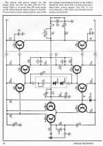
Here's the basic schematic of the original UT used in both the mono block and stereo versions, the boards are the same:
https://www.diyaudio.com/forums/att...217283-tiger-amp-madness-pe_oct_1970_pg32-jpg
The UT came in an open chassis mono block version and a closed chassis stereo version.
The stereo version used the same power supply but it was shared between the channels.
The mono block had one transistor per heat sink while the stereo version had the same
heatsinks but with 2 outputs on each one. They also deleted the thermal cut off in the
stereo version.
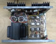
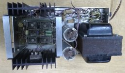
I bought this stereo UTS on ebay and it looks exactly like ours did when it failed, completely
burnt R12 and R14 with the board being charred even on the back side.
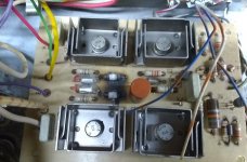
It is interesting that at audio frequencies and full power simulation shows about .9W in
R12, R14 and about the same in R15 and R16. The oscillation must be at high frequency
since plastic caps C3 and C4 melt and act to protect R15 and R16 forcing more power to
R12 and R14. The next and last revision of the UT increased R12 and R14 to 2W but left
the rest at 1/2 W when they also should have gone to at least 1W.
Here's a picture of the UTS from ebay with burnt resistors and melted caps on the top board:
https://www.diyaudio.com/forums/att...0684d1572213354-tiger-amp-madness-uts-top-jpg
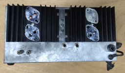
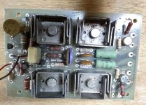
The next is a close up of the top driver board:
https://www.diyaudio.com/forums/att...572213747-tiger-amp-madness-uts-top-board-jpg
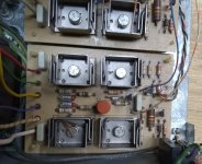
An odd thing is that often one channel has severe damage like the top board but then
often there are damaged parts in the other channel. I don't know the details of how this
amp from ebay failed but the lower board has R13 slightly burnt. I should test all the
parts on that board. R12 and R14 are mildly burnt and the caps partially melted:
https://www.diyaudio.com/forums/att...572215741-tiger-amp-madness-sut-bot-board-jpg
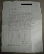
When our amp failed, back in the early 70s, I did the repair and wrote this letter to SWTPC:
I found this letter recently in a folder with equipment manuals and it is very interesting to
note that the diff pair transistor Q2 failed, as well as the feedback shunt resistor R8 and a
mild burn to R12 and R14. The violent HF oscillation in one channel leaked into the other
channel. It is also interesting that both drivers failed in the badly damaged channel but
only one output device failed since probably the negative rail fuse saved the other output
transistor. I was 12 years old when I built that amp and 14 when I wrote this letter:
https://www.diyaudio.com/forums/att...7d1572214249-tiger-amp-madness-uts-letter-jpg
More pictures of the Stereo UT:
Front, ours had a stick on brushed gold front panel but otherwise was the same:
https://www.diyaudio.com/forums/att...98d1572215850-tiger-amp-madness-sut-front-jpg
Back:
https://www.diyaudio.com/forums/attachments/solid-state/790699d1572215913-tiger-amp-madness-uts-jpg
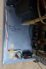
This one, actually a pair from ebay were built by Trout Audio Labs:
https://www.diyaudio.com/forums/att...00d1572216040-tiger-amp-madness-sut-trout-jpg
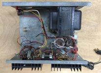
Here is the other in the pair from ebay, this one did not come with boards:
https://www.diyaudio.com/forums/att...01d1572216164-tiger-amp-madness-sut-2-top-jpg
There are several threads on here about various Tiger amps that were construction articles in
Popular and Radio Electronics back in the late 60 and early 70s. Many people have commented
about how they brought back memories and how they went up in smoke or
even (probably brief) flames. I'll share some pictures here for laughs.
I built and repaired the Lil'Tiger and Universal Tiger (UT) (stereo version) many times. I scratch
built the larger Tigersaurus that never failed.
The UT (stereo) I worked on is my parent's amp and over the years I've picked up a few on ebay,
and various members and friends have given more to me. Tubelab (George) here sent me
two nearly completed UT boards and a pair of outputs transistors from 1976.
Michael Chua (Ampslab) sent me 5 pairs of much newer output transistors from the 1990s.
A local friend bought a pair of Plastic Tiger boards years ago that he tried to run on +/-45V not
knowing that the 40V in the article was a misprint and should have been +/-30V - his went up in
flames on turn on. He later had plans to build many more amps and offered his home etched boards and parts.
I was given a UT MKII mono block with incorrect output devices, I'm sure that it failed at
some point.
Here's the basic schematic of the original UT used in both the mono block and stereo versions, the boards are the same:
https://www.diyaudio.com/forums/att...217283-tiger-amp-madness-pe_oct_1970_pg32-jpg
The UT came in an open chassis mono block version and a closed chassis stereo version.
The stereo version used the same power supply but it was shared between the channels.
The mono block had one transistor per heat sink while the stereo version had the same
heatsinks but with 2 outputs on each one. They also deleted the thermal cut off in the
stereo version.
I bought this stereo UTS on ebay and it looks exactly like ours did when it failed, completely
burnt R12 and R14 with the board being charred even on the back side.
It is interesting that at audio frequencies and full power simulation shows about .9W in
R12, R14 and about the same in R15 and R16. The oscillation must be at high frequency
since plastic caps C3 and C4 melt and act to protect R15 and R16 forcing more power to
R12 and R14. The next and last revision of the UT increased R12 and R14 to 2W but left
the rest at 1/2 W when they also should have gone to at least 1W.
Here's a picture of the UTS from ebay with burnt resistors and melted caps on the top board:
https://www.diyaudio.com/forums/att...0684d1572213354-tiger-amp-madness-uts-top-jpg
The next is a close up of the top driver board:
https://www.diyaudio.com/forums/att...572213747-tiger-amp-madness-uts-top-board-jpg
An odd thing is that often one channel has severe damage like the top board but then
often there are damaged parts in the other channel. I don't know the details of how this
amp from ebay failed but the lower board has R13 slightly burnt. I should test all the
parts on that board. R12 and R14 are mildly burnt and the caps partially melted:
https://www.diyaudio.com/forums/att...572215741-tiger-amp-madness-sut-bot-board-jpg
When our amp failed, back in the early 70s, I did the repair and wrote this letter to SWTPC:
I found this letter recently in a folder with equipment manuals and it is very interesting to
note that the diff pair transistor Q2 failed, as well as the feedback shunt resistor R8 and a
mild burn to R12 and R14. The violent HF oscillation in one channel leaked into the other
channel. It is also interesting that both drivers failed in the badly damaged channel but
only one output device failed since probably the negative rail fuse saved the other output
transistor. I was 12 years old when I built that amp and 14 when I wrote this letter:
https://www.diyaudio.com/forums/att...7d1572214249-tiger-amp-madness-uts-letter-jpg
More pictures of the Stereo UT:
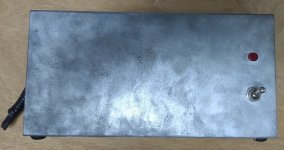
Front, ours had a stick on brushed gold front panel but otherwise was the same:
https://www.diyaudio.com/forums/att...98d1572215850-tiger-amp-madness-sut-front-jpg
Back:
https://www.diyaudio.com/forums/attachments/solid-state/790699d1572215913-tiger-amp-madness-uts-jpg
This one, actually a pair from ebay were built by Trout Audio Labs:
https://www.diyaudio.com/forums/att...00d1572216040-tiger-amp-madness-sut-trout-jpg
Here is the other in the pair from ebay, this one did not come with boards:
https://www.diyaudio.com/forums/att...01d1572216164-tiger-amp-madness-sut-2-top-jpg
Attachments
-
 UTS-TOP.jpg131.6 KB · Views: 2,170
 -
 UTS-TOP-BOARD.jpg129.8 KB · Views: 4,986
 -
 UTS-LETTER.jpg120.4 KB · Views: 1,863
 -
 SUT-BOT-BOARD.jpg136.2 KB · Views: 1,930
 -
 SUT-FRONT.jpg117.3 KB · Views: 1,769
 -
 UTS-BACK.jpg113.9 KB · Views: 899
 -
 SUT-TROUT.jpg110.8 KB · Views: 848
 -
 SUT-2-TOP.jpg162 KB · Views: 1,059
 -
 PE_Oct_1970_pg32.jpg139.9 KB · Views: 1,984
Last edited:
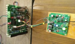
I finally pulled out this mono UT MKII and have started rebuilding it as an original to take
some measurements and try to observe the oscillation on the bench:
Started disassembling it, then remembered to take a picture:
https://www.diyaudio.com/forums/attachment.php?attachmentid=790703&stc=1&d=1572217979
Here is the MKII board with 2W resistors and transistors for output protection:
I started changing it back to the original design then remembered that I had good
new boards from Tubelab:
https://www.diyaudio.com/forums/attachment.php?attachmentid=790704&stc=1&d=1572218243
I decided to just finish one of the Tubelab boards that had never been powered up:
https://www.diyaudio.com/forums/attachment.php?attachmentid=790708&stc=1&d=1572218484
The soldering is not very good in all of the Tigers that I have so I'll be cleaning it up as I
rebuild it.
Attachments
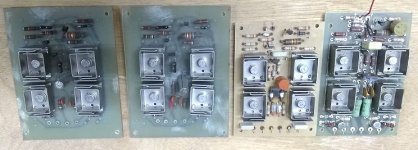
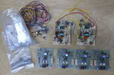
Here are the Plastic Tiger parts that a friend gave to me. Home made boards are in green:
https://www.diyaudio.com/forums/attachment.php?attachmentid=790710&stc=1&d=1572218769
I like the PT boards because they include many of the parts that are off board on the UT.
Thinking about turning them into a modded board for use with Darlington otuputs.
https://www.diyaudio.com/forums/attachment.php?attachmentid=790710&stc=1&d=1572218769
I like the PT boards because they include many of the parts that are off board on the UT.
Thinking about turning them into a modded board for use with Darlington otuputs.
Attachments
I owned a pair of Tiger amps (single 60V supply) and they were OK as long as you didn't short the outputs. That was when I learned how fuses fail right after the amp blows up. Its main problem was the wimpy heatsinks. Adding larger sinks was a major improvement along with having both outputs on the same sink so they tracked thermally.
The Universal Tiger with the MJ802 and MJ4502 outputs was a truly cranky amp with an annoying capability of oscillation.
Ah the (good) old days.
G²
The Universal Tiger with the MJ802 and MJ4502 outputs was a truly cranky amp with an annoying capability of oscillation.
Ah the (good) old days.
G²
...Plastic Tiger boards years ago that he tried to run on +/-45V not
knowing that the 40V in the article was a misprint and should have been +/-30V - his went up in flames on turn on.
I built several Plastic Tigers in as soon as the plans hit Popular Electronics. The magazine called for a 42 to 45 VCT power transformer. Those weren't available at Lafayette, Radio Shack or Olson's in 1971, so I tried a pair of 24 volt transformers. Playing music from the preamp at reasonable volume with 8 ohm speakers was not a problem. Plugging in my guitar and blasting away resulted in two output transistors that were split in half. I wound my own power transformer eventually that put a lower voltage on the parts and all was well.
I got a job at Motorola in 1973 and myself and some friends built lots of Li'l Tigers, Plastic Tigers and Universal Tigers. The Li'l Tiger with some upgraded output parts was indestructible, full on guitar crank into a dead short just made the power transformer hot. Both the Plastic and Universal Tigers had a propensity for random oscillation on squirrely loads that could often result in scattered parts.
We used whatever transistors the Motorola Semiconductor sales rep told us was the "best" parts available at build time, and some were house numbered, so I have no idea what was in the old boards I had. Some of the UT's did have the proper RCA driver transistors, TO5's with welded on heat sinks.
After I sent you the box of parts several years ago, I found another box of boards that we had made in the same time frame (73 through about 80 or 81). I packed up everything and moved 1200 miles in 2014 when my 41 year career at Motorola ended. I haven't seen those boards since I got here, and they probably got tossed before the move, but I will let you know if I find it.
George, I have to say thanks to you and everyone else who's sent parts to me!
All the best to you all.
All the best to you all.
My plans are to first rebuild and figure out and solve the basic problems with the UT design.
Then to use whatever is needed from the Brystons to make a stable version with a Darlington
output stage capable of driving 4 or even 2 ohm loads, and use modern devices.
Then to use whatever is needed from the Brystons to make a stable version with a Darlington
output stage capable of driving 4 or even 2 ohm loads, and use modern devices.
Lament for a Tiger
Tiger tiger burning bright,
your output circuit is black as night
Your front end looks great
but its the overall oscillations that we hate
They are, we fear, linked to that Output stage
and that really shows your age
For the culrpit is that common collector
that really screws the transfer vector
We see excess gain and poles galore
and then, just when we thought it safe, even more
no miller capacitor just like Doug told us
this I tell you is why there is a fuss!
So friends, lets ditch this burning design
and go for something a bit more benign.
Wow, I thought I was extreme messing with dynaco ST120's.
With 5 extra transistors/channel (djoffe mod) they actually sound good. With 2 fans on the "heat sinks" the output transistors will actually last.
SWTC was just down the road from Houston & I built a couple of their kits. The "sea sounds" module lasted 9 months. End of my interest. I'm glad now I couldn't scrape together the $$$ for one of their amp kits. The dynaco ST120 has only gone up in flames twice. Once before I bought the hulk, once before fans. I'm listening to it now in fact, about 10 hours a day.
Last edited:
The high frequency oscillations these things can develop would not be nearly as destructive if the output stage was Baker clamped. It would also have more benign clipping. There are several well respected pro amps that use similar output stages and even with gains of greater than 2X, and driven by op amps to give even more loop gain. They use Baker clamps and darlington outputs. Check out the QSC PLX series schematics and see how similar it is to the Tiger. And it will give you a good idea how to fix the Tiger.
And while you’re at it, the VAS stage needs current limiting of some sort. The way it is, typically you’ll blow up your outputs from rail sticking and the common mode conduction that results before that becomes a problem, but it would be the next domino to fall.
And while you’re at it, the VAS stage needs current limiting of some sort. The way it is, typically you’ll blow up your outputs from rail sticking and the common mode conduction that results before that becomes a problem, but it would be the next domino to fall.
The high frequency oscillations these things can develop would not be nearly as destructive if the output stage was Baker clamped. It would also have more benign clipping. There are several well respected pro amps that use similar output stages and even with gains of greater than 2X, and driven by op amps to give even more loop gain. They use Baker clamps and darlington outputs. Check out the QSC PLX series schematics and see how similar it is to the Tiger. And it will give you a good idea how to fix the Tiger.
And while you’re at it, the VAS stage needs current limiting of some sort. The way it is, typically you’ll blow up your outputs from rail sticking and the common mode conduction that results before that becomes a problem, but it would be the next domino to fall.
I think you're right on the money here, I also believe that the bandwidth drops dramatically
when the rail sticking happens and that probably induces the oscillation. I'm thinking that
removing C8 and using MIC from the VAS back to the inverting input is the way to go.
Thanks very much for the reference to the QSC PLX amps - I will certainly take a look.
Do you have a link to the schematic?
Last edited:
eserviceinfo.com says they have the plx1802 schematic.
QSC PLX1802 amplifier - Service Manual Free Download
I wonder how few changes you can make to a universal tiger or plastic tiger (the worst ones I heard) to make a reliable amp out of one? Can the original PCB be patched?
eserviceinfo is requiring I install a missing driver for windows 7,8,10. I don't use windows, I use lubuntu 14 flavor linux. So I can't download from eserviceinfo anymore I suppose.
Last edited:
Hi Pete,
As Bonsai said, better to use a newer improved design than try to re-work that older design.
I can offer you a few blank pwb's that I did up for Bob Cordell's BC-1 power amp design as detailed in chapter 4, in his 2nd edition book.
The BOM is loaded as a Mouser shopping cart.
Caveat, they perform quite well according to Bob's wealth of testing. We will be doing a minor pwb revision, so I have a few IPS/VAS pwb's that I can offer you. The O/P stage, protection pwb's I have 2 left ( I only ordered 5 of them initially), not sure if they will work mechanically in your case.
As far as providing you with details, I would have to ask Bob if I can publicly release this information or make you sign a NDA 🙂 If you have the 2nd edition book then you already have what is needed and I can provide the addition info.
Rick
Attachments
OMG this takes me back. I dreamed of making one of these but I was too poor. I managed a lil-tiger as my sub amp which I rebuilt a couple times (with ~TIP33/34) which I used with (also rebuilt) Sinclair amps and a Akai reel-reel.
Has anyone done a thorough spice model of this amp? I suspected some of the things Bonzai suggested but I'd like to do a simulation to check it out.
Later I did build a quasi that had a strange problem with the 40409 VAS required moving the miller cap to the bottom of the board because a small loop of board trace was enough inductance to make a VHF oscillator.
BTW, I think that 390 R9 in the emitter of the VAS will prevent the VAS from blowing up?
Last edited:
Hi Pete,
As Bonsai said, better to use a newer improved design than try to re-work that older design.
I can offer you a few blank pwb's that I did up for Bob Cordell's BC-1 power amp design as detailed in chapter 4, in his 2nd edition book.
The BOM is loaded as a Mouser shopping cart.
Caveat, they perform quite well according to Bob's wealth of testing. We will be doing a minor pwb revision, so I have a few IPS/VAS pwb's that I can offer you. The O/P stage, protection pwb's I have 2 left ( I only ordered 5 of them initially), not sure if they will work mechanically in your case.
As far as providing you with details, I would have to ask Bob if I can publicly release this information or make you sign a NDA 🙂 If you have the 2nd edition book then you already have what is needed and I can provide the addition info.
Rick
Hi Rick, That looks a bit complex. I don't have Bob's 2nd edition yet but will probably get it if it goes on sale, Black Friday maybe.
I could try out those boards in the chassis that is missing boards.
PSU is +-42V
OMG this takes me back. I dreamed of making one of these but I was too poor. I managed a lil-tiger as my sub amp which I rebuilt a couple times (with ~TIP33/34) which I used with (also rebuilt) Sinclair amps and a Akai reel-reel.
Has anyone done a thorough spice model of this amp? I suspected some of the things Bonzai suggested but I'd like to do a simulation to check it out.
Later I did build a quasi that had a strange problem with the 40409 VAS required moving the miller cap to the bottom of the board because a small loop of board trace was enough inductance to make a VHF oscillator.
BTW, I think that 390 R9 in the emitter of the VAS will prevent the VAS from blowing up?
Yes, that is true, don't think I've ever seen the VAS or the current source load ever fail.
I spiced the UT here, look later in the thread where I used Bob C's semi models, the others
are not good: Swtpc Universal Tiger Improved And Simulation
I also did the Tigersaurus:
SWTPC Tigersaurus 250W Amp Simulation
And the Bryston which borrows a lot from Tigers:
Bryston 3BIII SPICE Simulation
Last edited:
eserviceinfo.com says they have the plx1802 schematic.
QSC PLX1802 amplifier - Service Manual Free Download
I wonder how few changes you can make to a universal tiger or plastic tiger (the worst ones I heard) to make a reliable amp out of one? Can the original PCB be patched?
eserviceinfo is requiring I install a missing driver for windows 7,8,10. I don't use windows, I use lubuntu 14 flavor linux. So I can't download from eserviceinfo anymore I suppose.
Found this, sure is complicated:
http://bee.mif.pg.gda.pl/ciasteczkowypotwor/SM_scena/QSC/QSC_PLX_Series_Service_Manual.pdf
- Home
- Amplifiers
- Solid State
- Tiger Amp Madness!