Hi, Nelson!
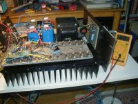
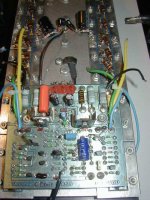
I bought this amp about 20years ago, second hand and I have no idea on what was done before...
I noticed some discrepencies with the plans I found on Diyaudio but the amp was fine sounding for all these years, until it showed some oscillation problems...
As for visible modifications, i had to put some new binding posts at the speakers and ground solder lugs, as too much soldering had burned the tracks...
added some local decoupling caps on the power boards, you can see and some caps on the underneath of the pcb.
of cource main caps were changed to 22.000/100v BC with bypass polypropylene...
the VBE transistor in now under the PCB
some bleeders resistors to discharge the reservoir caps in the test process but will be removed when the amps are OK
but otherwise the circuit was not changed!
Well it's been a while since I had these oscillation problems,
BTW I' looking for a couple of replacement PCB, because, you know, desoldering and soldering dont leave the tracks undamaged...
best regards
Attachments
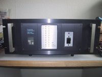
Thanks a lot for all the information, docjoe🙂 I will read through the threads you listed, and try to follow your advice. I did find out one thing though. The peak meter lighting up on one channel, is a fault in the display circuit itself. There is a switch on the rear that can turn the leds on/off. Even in the off pos. they keep lighting in left channel and turns off nicely in the right channel. Somebody obviously got tired of looking at the lights, once. So he mounted a switch. It was not the current owner.
Anyway, here are a few pics.
Steen🙂
Anyway, here are a few pics.
Steen🙂
Attachments
HI,
I do not have this switch on my amp!
can you put me a diagram of the switch wiring assembly?
have ou a dc offset on the faulty side? and how much?
I do not have this switch on my amp!
can you put me a diagram of the switch wiring assembly?
have ou a dc offset on the faulty side? and how much?
Hi doc. The switch is not on the original amp. The guy who made it, took the two peak-sensing leads on the outputs and soldered them to the switch and soldered two other leads from the switch to the outputs. In that way it is possible to break the signal that goes to the front peak display. I can post a close-up picture tomorrow. I just assembled the amp so I could take a good listening to it on my own system tomorrow.
Steen.
Steen.
I have been busy😡 Just took a good listening session with this amp. It is louder on the left channel for sure. Also the right channel gets hotter on the heatsink, so I recon its the oscillation thing, allright. It measures like 10 deg. C more than the left cannel. As for DC offset, it is not a lot; left channel is 0,020v right channel 0,034v's. So the bad channel has more offset, no surprise. Otherwise the listening session was fabulous😀 Except for the lower output of the right channel, it sounds really good🙂 I could drive my ProAc clones to high volumes, with really good control. The offset is measured with music playing, right at the speaker binding post's.
As a sidenote, I have to mention this odd thing; On the rearplate the right side says left, looking aft from the front and the left channel says right I think someone screwed up😀 If the silkscreen is correct, you have to cross the speaker cables😀 😀
Steen😎
As a sidenote, I have to mention this odd thing; On the rearplate the right side says left, looking aft from the front and the left channel says right
I think someone screwed up😀 If the silkscreen is correct, you have to cross the speaker cables😀 😀 Steen😎
😀 😀Unless the owner is cross-eyed !
Hi Jaccoboy! You are right, it is really an amplifier!! If it was my own, I would propably restore it😉 Now, I dont think I will use all those ours, to replace everything, like the doc did
 I dont know, maybe this winter, if I need something to work on😉
 A Threshold Stasis isn't just any amp😉 Still, the damping factor must be brilliant, as it really controls the speakers🙂
Steen😎
hi steenoe and jacco
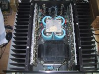
now i've completed a first 12 hours run.
the temp is about 40 ° C. and bias set 0.75 amp on both channel; offset is 10 mv on one chanel and 60mv on the other...
have to trim those 47R and 33R resistors in the diff pair, as I changed these to BC550c.
yes you have to cross the speaker wires, unless you display the back of the amp in your setup.
Attachments
Thats a pretty sight, doc😉 I really do not get this right/left thing on the rear panel😀 Hmmm, I guess my old friend has to wait a bit, before his amp is getting fixed! I simply do not have the time at this point, to make a larger restoring Doc, do you have a specific opinion about what is causing the oscilation?? Maybe the Tantal's as you mentioned, or the trimpots?? If I had something specific, I might give it a shot😉 Thanks in advance🙂
Steen😎
BTW I measured 40 deg C on the healthy channel and 50 deg C on the other.
Doc, do you have a specific opinion about what is causing the oscilation?? Maybe the Tantal's as you mentioned, or the trimpots?? If I had something specific, I might give it a shot😉 Thanks in advance🙂 Steen😎
BTW I measured 40 deg C on the healthy channel and 50 deg C on the other.
docjoe said:
yes you have to cross the speaker wires, unless you display the back of the amp in your setup.
Hey guys, your not serious, are you???
To read them correct you must end those comments with a

As a matter of fact, this is actually correctHey guys, your not serious, are you???
At first I did take several readings on the rear panel, and had to conclude the facts: they actually swapped right/left on the silkscreening Well, the guy doing this could be somehow excused, I guess😱 Looking at the rearpanel from aft, would imply that the right channel is at the left and "vica verca"
Steen🙂
yes that' correct, but I presume that for maintenance point of vue, if you work on it, the PCB, are on the back as are the bias pots, its seems easier to .
anyway even if they crossed sides, the diode bargrap display is ok!
anyway even if they crossed sides, the diode bargrap display is ok!
Just to let you guy's know, I decided to deliver the amplifier back to the (unhappy ) owner at this point It was quite a hard decision, but I simple do not have the time for a major workover at this point. Besides, it is way too hot in Denmark, to do big soldering jobs right now Thanks a lot for your inputs, anyway🙂 I will keep you posted if (probably when!)
I take it it on again🙂
Steen
) owner at this point It was quite a hard decision, but I simple do not have the time for a major workover at this point. Besides, it is way too hot in Denmark, to do big soldering jobs right now Thanks a lot for your inputs, anyway🙂 I will keep you posted if (probably when!)I take it it on again🙂
Steen
What, you guys in Denmark dont have air conditioning?
well in Paris it is about 20°c now
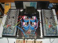
Well I think I've finished my rebuilt, I hope it will last another 25 years...
I'll be pleased to hear about you...
well in Paris it is about 20°c now
Well I think I've finished my rebuilt, I hope it will last another 25 years...
I'll be pleased to hear about you...
I am sure we have like 30C now, I feel for a swim right now! Lucky enoughwell in Paris it is about 20°c now
to have Denmarks nicest beach, 500 meters away😀 Well, the guy actually took the hole thing in a cool way. He would look for a ML! He has a pair of big Apogee clones, and they really demand some power. Those darn speakers, which are very well build indeed, are the size of a door😀 But the impedance is hopeless😉
Otherwise, I would have made an Aleph for him, of course😀
The chassis with heatsinks could house an Aleph 5😉
Steen😎
- Home
- Amplifiers
- Pass Labs
- Threshold Stasis 2.