Speaking about Keith Jarrett:
I just got me The Cellar Door Sessions 1970 6-CD box
I just got me The Cellar Door Sessions 1970 6-CD box
lumanauw said:
I want to write about my own (myself) experience. Something that I do not understand until now, is that why many "good" things in textbook do not result in the sonics that I wanted?
For example, there was time that I build cct's with very good regulators, cap multiplier etc. The sound is just "dead". Now I only use 1 R and 1 Cap forming pi-filter, and to me (myself) it sounds better than using complicated rail filter with many semiconductors. Again here I don't know why it is so to my ears. Using passive components (R-L-C) seems to sounds better to me than using semiconductors for rail filter (again : not for anyone's else's ear 😀)
I make many cct's that will be blamed "wrong" from technical POV. I have books like DougSelf's kind of technical book, have built cct's based on those book's tutorial, but now I just make cct's based on 2 pages of Keith Jarret's Foreword in "Complete Guide to High End Audio" by Robert Harley. It helps me to convince myself when I'm making a "technically-wrong" audio cct's 😀
lumanauw said:Question : what do you read in those 2 pages?
There are no "THD" or "S/N ratio" or "Damping factor" word in it. But for me it gives a clue what the "average ears" are looking for. ("average ears" here = everyone who don't design audio amplifiers or have soldering iron in their hands). If the music is sad, you have to be sad hearing the reproduction. If the music is happy, it has to make you happy hearing the reproduction. It's difficult to approach this, and strangely, this characteristic very often can be achieved with cct or approach that is said "wrong" in technical textbooks.
Lumanauw,
That’s a very interesting experience and point of view.
My previous experience dictated that I should have some sort of regulation on line amps, have done most sorts of PSU including L-C but for power amps and have never test these on preamps. Should give it a try, both of them R-C and L-C plus the previously proposed Shunt, I’m sure this will be a very enlighting experience.
Thanks for the input and those scannings from Keith Jarret. 😎
apassgear said:Yes Choky, I do remember your comments. And we do have a quest to find the best reg for this stage. So we should test whatever with deem adequate.
I’m determinate to squeeze the best from the NS10 and think it will also be a good mate for the Babelfish. The idea of a high performance BJT linestage is really appealing, be it with JFET input or not. 😉 😎


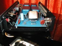
yeoldestereo said:In case anyone is interested I have a NS 10 that was recently updated by Jon Soderberg of Vintage Amp Repair.😀
However upon delivery back to me FedEx Ground did handle the package properly and was damaged.
The on/off switch was broken off and the transformer was dislodged from its mounting prongs.
So if anyone here has a need for one of these let me know. It is repairable, cicuit board not harmed.
At 63 now I am no longer in the diy game.
Anyone interested kindly e mail me with any info you may need and additional pics.
My best to all🙂
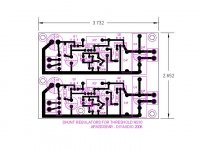
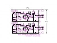
apassgear said:I decided to open yet another NS10 thread, this one is about building a lineamp as close as possible to the original thing with some update ideas.
This has been possible thanks to R-K (Rolv Karsten) who posted a schematic he kept for 27 years that appeared to be faithful to the original in words of Nelson Pass, besides that there were many other valuable contributions such as close up pictures of the naked boards (sans cans) of the line and RIAA PCB’s by Malotron and others. Thanks to all you great guys again.
http://www.diyaudio.com/forums/showthread.php?s=&threadid=67915&perpage=10&pagenumber=49
The idea behind this layout might not be for everyone since I took some “non audiophile” route regarding input and output caps which are not MKP’s but had my reason to it. Laying film caps on the board crated an awful appearance and did not look neat and ended with a big PCB for each channel. So I decided to keep the original spirit and go with lytics and thought that today’s caps are way better than 25 or 30 years ago, so why not?... use some BG or Panasonic FC’s which are way better than the old ones and in some cases being preferred to film caps by some DIY’s. The only big film cap is at the rail decoupling.
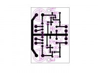
Since I wanted short traces and a compact layout I also decided to use the smaller ½ W resistors with an over all length of 0.360” (9.15mm) so no Dales RD-55’s, though I know in some places on the layout it is possible to add longer lead resistor and could add some pads, but for the time being only short resistors are possible.
All 3 signal BJT are as close as possible and the overall signal path is as short as it gets with these type and size of components which was one of the premises I started with, so I expect that the overall performance of this layout be quite good.
The overall size of the PCB is 3.110 X 2.125” (79 X 54 mm) one sided and uses no jumpers so its easy to etch and build. Most of the traces are 0.035” (0.89 mm) smaller pads are 0.080” (2mm) really don’t know how difficult could be to etch this by oneself with the regular photocopy transfer process. Any ideas?
Related to the bias opamp I decided it should have double rails for best stability and this enable to use any type with standard pinout you may have at hand, rails then should be 18/15 +-V. It’s a single unit DIP so one on each channel as the Master did.
I will welcome all suggestions so please chip in to make this layout better.
R-K Rønningstad said:I found what I believe is really the original NS10 schematics, thanks to my brother-in-law, who had a folder with quite a lot of stuff!
If versions of the NS10 exists I do not know. Nelson probably will know!
I think this is basically identical to the one I posted some time ago, but that schematics was probably something I hand copied from this one now attached!
Rolv-Karsten


apassgear said:
R-K
Wow, thanks again, excellent contribution, Rolv. We now have both line and RIAA stages.
As you say, I guess the previous schematic (RIAA one) was drawn from this one taking in consideration the notes appearing on this schematic. So I would venture to say that both are correct.
So now we are headed to the real thing having all the values correct!!!!
😎 😎 😎
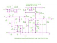
apassgear said:For clarity I have redrawn the schematic which is a guide also for the PCB with numbered components.
I have also marked components with a “*” that are not part of the original design. These values, if used, should be tested for best performance.