Hi guys,
I've been looking at Mouser.
This is probably fine for C3:
http://ca.mouser.com/Search/ProductDetail.aspx?qs=iLKYxzqNS7510NMz3/xT3w==
Price isn't bad and there's a decent supply.
For C1:
http://ca.mouser.com/Search/ProductDetail.aspx?qs=olJun0bQHM//LvASv5mnvA==
I wonder what the min order quantity is when stock runs out?
Steen has suggested include a double Raw Supply PCB on the GB, maybe a single scored board containing 2 Regs and the double Raw Supply. I have a design for it which Steen has reviewed… I’ll post it later for everyone to see and give opinions.
apassgear said:That’s great Magura, thanks... maybe that will also take care of Americas. Any idea on cost for those parts?
In the other hand I have found suitable MKP’s around here one brand from Illinois Capacitors (IC) on 5 and 7.50mm lead spacing for C1 and C3 from Allied, availability has to be check though.
A second alternative is Vishay 1841 MKP’s from Newark on 7.50mm leadspace at less than 0.50$ apiece, seems a good candidate also, availabitity has to be checked.
Still pending to check C2, I’ll do that later.
🙂
Tell me what you need, and I'll give you a pointer regarding the price. This is real cheap though. Both Steenoe and I have bought loads from this source.
Magura 🙂
Link to the surplus from this shop.
Yes, I realize it's in Danish, but should not be too hard to make sense of.
http://elektronik-lavpris.dk/campaigns.php?campaign=3
Magura 🙂
Yes, I realize it's in Danish, but should not be too hard to make sense of.
http://elektronik-lavpris.dk/campaigns.php?campaign=3
Magura 🙂
Magura said:Link to the surplus from this shop.
Magura 🙂
Gee man, I hope I had a toy house like that around here.
I'll be back on this one and see if we may have some caps there.
😎
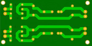
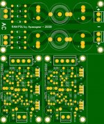
apassgear said:This is the idea of the double raw supply plus two scored reg boards.
Comments?
Perfect ... as usual capitano.
Sorry for having disppeared last days but ... bloody busy ..
Manu
Attachments
Great work guys on the raw power supply PCB layout. I am so looking forward to building this for my B1.
Cheers
Dave
Cheers
Dave
Hey Manolo, great work as usual.
Couple of minor details.
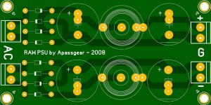
Looking at your very nice artwork I see you marked both raw supplies as positive; of course both could be used to do either polarities so I think maybe if we mark one for each polarity could be more universal. I see negative polarity orientation of caps for the upper one but diodes need to be flipped to go for negative.
On the other hand we should change the marking on the silk screen to show negative and maybe instead of a minus sign at the center I think is better to show a G for ground.
Could we move a bit to the center both of those AC screw connectors to leave more space for mounting screws?
Cheers,
😎
BTW, what lead space did you give to the lytics?
Couple of minor details.
Looking at your very nice artwork I see you marked both raw supplies as positive; of course both could be used to do either polarities so I think maybe if we mark one for each polarity could be more universal. I see negative polarity orientation of caps for the upper one but diodes need to be flipped to go for negative.
On the other hand we should change the marking on the silk screen to show negative and maybe instead of a minus sign at the center I think is better to show a G for ground.
Could we move a bit to the center both of those AC screw connectors to leave more space for mounting screws?
Cheers,
😎
BTW, what lead space did you give to the lytics?
Ooooppps!
Sorry about flipping the polatities for the diodes, they are shown on the correct orientation so only need to change the silk screen markings.
😉
Sorry about flipping the polatities for the diodes, they are shown on the correct orientation so only need to change the silk screen markings.
😉
Great, dead on.
Now, another minor detail, when seeing the last artwork, we might be able to move a bit the mounting screws towards the center, they look too close to the edges and now we have more space there.
I didn’t sent you a layout with dims, my fault, but I had left the shortest leadspace for the inductor at 7.2mm good for the MuRata 18R473C (DK 811-1313-ND) cored choke, but can’t measure your layout.
On the regs, yes, we could do both polarities, and mark them on the silk?
Hi,
Shortest lead space of inductor is also 7,2 mm
I ll slightly move mounting screw position.
(BTW dims of posted board are 100x50 mm)
Any idea about something to fill free space on panel?
(Fuse killer would be fine ... 😀
http://www.diyaudio.com/forums/showthread.php?s=&threadid=133533 )
)

Manu
Shortest lead space of inductor is also 7,2 mm
I ll slightly move mounting screw position.
(BTW dims of posted board are 100x50 mm)
Any idea about something to fill free space on panel?
(Fuse killer would be fine ... 😀
http://www.diyaudio.com/forums/showthread.php?s=&threadid=133533
) Manu
Great job guys!
A couple of questions: Do you think it's beneficial to
modify the PS board slightly to allow easier use
of TO220-sized diodes?
I'm also wondering about heatsinking of the transistors
on the regulator board. It doesn't look like you can
just put the mount the regulator board up against
a heatsink. Do you think something relatively
small (such as a small L-shaped piece of aluminum
mounted to the transistors), will be sufficient?
Thanks,
Dennis
Hi Manu,
I'm working a bit on my Toole Reg this weekend, got the boards from my local shop.
But i searched for the diodes for the raw supply and find no reference to them...i have quite a few MUR 860 here at home...but i suspect that you are using others, judging from apparent spacing in raw supply board, is that so ?.
😉
By the way...thanks a ton for super reg boards.
Dennis Hui said:Great job guys!
A couple of questions: Do you think it's beneficial to
modify the PS board slightly to allow easier use
of TO220-sized diodes?
I'm also wondering about heatsinking of the transistors
on the regulator board. It doesn't look like you can
just put the mount the regulator board up against
a heatsink. Do you think something relatively
small (such as a small L-shaped piece of aluminum
mounted to the transistors), will be sufficient?
Thanks,
Dennis
T0-220 diodes? Yes, but we have to adapt the traces to the spacing as RM5 is not a lot and don't allows big traces fooling around the pins ...
There are nice Onsemi schottky in D0-41 or D0-201 which would nicely fitt in the actual size...
But as you like it boys...
The best way to cool the transistors of the regs will certainly be to screw them to the chassis (bottom plate or side plate) with carefull isolation.
A piece of Alu would do the job , though.
Manu
- Status
- Not open for further replies.
- Home
- Amplifiers
- Pass Labs
- Threshold NS10 Lineamp PCB