OK - hard for me to judge 🙂
I noticed that the PSU does not use the two 24 regulators seen in the earlier pictures this one uses a TO3 style transistor, and only one capacitor (not a balanced psu with x - 0 -X volt but 0-x volt?
Also, I see several more of the 10uF coupling caps - also can't find the capacitor values on the previously posted schematics....
Best regards
Hans
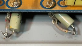
Another question.... A friend of mine is trying to trace where some of the noise in the Phono input of my FETII series 1 could come from. Found two small 150mh coils at the input of the RIAA circuit - see attachment. Wondering why they are there? When you put a metal screwdriver near them, the hum rises considerbly - we suspect they act like small antennas ....?
Attachments
Last edited:
Hi ZenMod - I have of course thought of it, but what if they were meant to be there? won't I rist sending the JFET's into ultrasonic oblivion if it's meant as protection to them?
Best regards
Hans
Best regards
Hans
Does anyone happen to know the input impedance of this preamp? Is it pretty much dependent on the first parallel resistor?
Thanks
Thanks
- Home
- Amplifiers
- Pass Labs
- Threshold FET 2