That would make it 2 MHz. I don't think a failed capacitor would cause that.
I sent the unit to Threshold a month ago, they replaced the remote power supply filter capacitors and declared it "fixed". After paying $350 for new filter cap's and a declaration of a repair, I'm now in the position of either I fix it or throw it away/store on shelf in basement forever.
I sent the unit to Threshold a month ago, they replaced the remote power supply filter capacitors and declared it "fixed". After paying $350 for new filter cap's and a declaration of a repair, I'm now in the position of either I fix it or throw it away/store on shelf in basement forever.
So it is not a "Pass Threshold" amp?
Could it be a bad capacitor in the feedback loop.....if amp has feedback?
The oscillation in one channel could afect both channels as they have common PSU?
Could it be a bad capacitor in the feedback loop.....if amp has feedback?
The oscillation in one channel could afect both channels as they have common PSU?
What would cause high frequency in the - input side of the gain boards but not the positive side of the gain boards?
Does the feedback line from output go to the -input? …..just a wild guess….I am not expert in this…...and I don't know if amp has global NFB.
Yes, it is a Pass designed Threshold Phono section.
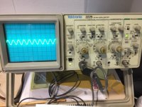
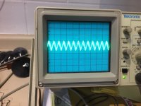
Here are pictures of the scope pattern for the output of the gain boards, two boards have lower voltage output as seen in the second picture.
The same scope pattern is on pins 19 & 20 (output), pins 15 &16 (comp 1), pins 17 & 18 (comp 2) on each gain board.
Here are pictures of the scope pattern for the output of the gain boards, two boards have lower voltage output as seen in the second picture.
The same scope pattern is on pins 19 & 20 (output), pins 15 &16 (comp 1), pins 17 & 18 (comp 2) on each gain board.
Attachments

Maybe the "fix" of the PSU caps at threshold has caused this error…..maybe the amp is sensitive of which type of caps…...if ESR is not low enough….or whatever....so to fix one error a new error is introduced?
take a good look at schematics
I'll be back on Sunday ........ if nothing else , to make a mess as usual

I'll be back on Sunday ........ if nothing else , to make a mess as usual
There is feedback from output to - input with the jumper set to MM. When I select MC, I get a very nice sine wave on both inputs + & - along with output. As soon as I select MM, the pattern has high freq on the - input to the gain stages. Here is a picture of the - input with the jumper on MM and two gain stages removed.
Attachments
I removed all four gain stage boards and followed the input signal across the main board with nothing showing up weird. Once I install a single gain stage, everything is fine if MC is selected, once I select MM, I get high freq. to - input.
There is a feedback cap C2 = 39pF back from output to Input - ?
This cap should prevent oscillation?
But maybe condition has changed after filter caps has been renewed?
This cap should prevent oscillation?
But maybe condition has changed after filter caps has been renewed?
After all it seems like a "minor" problem to get the amp stable again…..with all the experts in this forum..... 🙂
Did Threshold replace the small electrolytic caps on the Secondary Power Regulator Boards and the one or two on the Mobo?
It sounds like whatever is happening is common to both channels, and your 10-p seems pretty similar to my FET-9 (but broken-up into more separate modules, with Op-Amp servo mechanisms maintaining the biasing rather than the earlier discrete design?)
Another thing to try might be to hook-Up some batteries or a Lab Power Supply and try injecting an external DC source of correct, regulated Voltage (one side at a time) with regulator Modules removed and see if the problem goes away (does that channel then WORK?). That could at least isolate the problem to a SECTION, then dive deeper into that section.
I’m no expert at component-level repairs / troubleshooting - but I AM a big proponent of “Divide and Conquer” where I can...
It is not power supply issue, I have a steady +18vdc and -17.9vdc on both rails and to each of the four gain boards.
rayma - I have a pair of x10 probes which give the same scope pattern for the output, with only a 4mV input, the x1 probe works best tracing the input signal.
I ordered new polystyrene capacitors, since I suspect the .001uF (C102), because I'm going to replace caps, I'm also replacing C103, C104, C105,C106. All of these are SEC polystyrene capacitors.
I should know the results after new years.
- Home
- Amplifiers
- Pass Labs
- Threshold FET-10e Phono