My Threshold FET-10e Phono preamp died a couple of months ago, both channels have very low gain, almost a whisper. I'm using a MM cartridge and have the dip switches set to 47k and 200pF. All four gain switches are set to MM. I lived less than a mile from Fermi Lab and have had several TV's and two channel stereo equipment fail due to transformer failures and spikes in line voltage from when Fermi Lab fires up the particle accelerator.
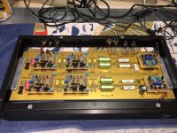
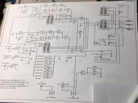
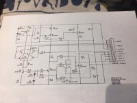
Now that I have moved, it's time to try to fix the FET-10e so I can listen to vinyl again. Here are pictures of the preamp.
Now that I have moved, it's time to try to fix the FET-10e so I can listen to vinyl again. Here are pictures of the preamp.
Attachments
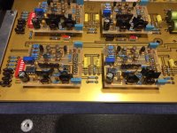

There are four gain boards as this has balanced outputs (XLR) along with RCA's. The lack of output is with both the XLR and RCA's.
First hing I did was check the remote power supply voltage, I have +27.5vdc and -27.5vdc going into the preamp. I checked the regulator section of the preamp and measured +18.0vdc and -17.99vdc at all four gain boards and the rail traces on the PC board.
Next I put a 1K sign wave at 4mV into the MM input and went searching for A/C and D/C voltage at the outputs. XLR pin 1 = 0 v A/C and D/C to ground. Pin 2 has 0.08v (L) and 0.11v (R) A/C to ground With pin 3 = 0v.
On pin 2, I found -10vdc on both the left and right channels, the odd thing was as I had the DMM hooked up to pin 2, the voltage would decrease, when I removed the DMM, the final reading was -8.5vdc. Then when I connected the DMM again to pin 2, it measured -8.5vdc and started to go down in voltage again. Every time I removed the DMM from pin 2, and then connected it again, it would measure the same D/ voltage as when I removed the DMM and start to decrease towards 0V.
have schematics?
they're everywhere on forum
if everything is silent , check function of muting relay
they're everywhere on forum
if everything is silent , check function of muting relay
When both channels are nearly silent then the logic says that is must be the power supply which is common for both channels. Does DC voltages look good using oscilloscope?
If it is not the power supply and both channels gets silent…..then something "wild" has happened?
If it is not the power supply and both channels gets silent…..then something "wild" has happened?
I checked the muting relay and it was functioning correctly with the outputs shorted to ground with power off, with power on it clicks and the outputs are no longer shorted to ground.
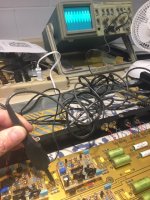
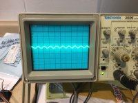
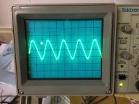
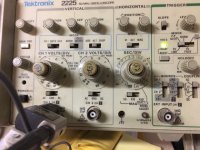
Using my decades old Tectronix 2225 scope, I went looking for my 1K sine wave, sure enough a nice sine wave at +input to each gain boards, however when I tested - input all was not well. The scope pattern was increased voltage and what looked like D/C with the sine wave.
Using my decades old Tectronix 2225 scope, I went looking for my 1K sine wave, sure enough a nice sine wave at +input to each gain boards, however when I tested - input all was not well. The scope pattern was increased voltage and what looked like D/C with the sine wave.
Attachments
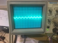
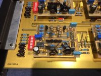
The second picture is when I probe R107 to R104. When I probe each gain board the pattern has less sine wave characteristics to it.
Is this caused by capacitors C102 (1nF) and C103 (3.6nF) leaking D/C?
There are four sets of these capacitors and they all have the same scope patterns.
Is this caused by capacitors C102 (1nF) and C103 (3.6nF) leaking D/C?
There are four sets of these capacitors and they all have the same scope patterns.
Both the + rail and the - rail are dead flat on the scope, little to no ripple that I can measure.
On first scope pictures there are some heavy spikes on sine?
Is it oscillating?
2. pictures looks like a high frequency that are modulated with 1 kHz sine?
Is it oscillating?
2. pictures looks like a high frequency that are modulated with 1 kHz sine?
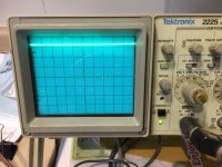
I'll take another photo of the + input sine wave and then a picture of the -input signal to all four gain boards.
I'm not sure if the first pic are spikes or reflections, the second picture is very similar to the -input pattern.
Is that what high freq modulation looks like?
I'm not sure if the first pic are spikes or reflections, the second picture is very similar to the -input pattern.
Is that what high freq modulation looks like?
To my eye it looks like a high frequency. Try to sweep faster using the time base to see if you can trigger on the high frequency……..if it is a high frequency.
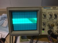
The 2. picture looks like it is oscillating. Try to adjust time base.....to look closer at the high frequency…..turn clockwise…...until you see a clear signal......
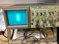

Also the two other scope pictures…..they don't look clean…...try to turn time-base clockwise also on these with dim light in the room to see if a higher frequency shows up. It is here an analog scopes has its advantage…..it can display fast spikes…..
- Home
- Amplifiers
- Pass Labs
- Threshold FET-10e Phono