
It is difficult to offer advice in a case like this.
ZM is right. If you are buying, then S300, but building is always the best...

ZM is right. If you are buying, then S300, but building is always the best...
Hi all, I am looking for the instruction manual for CAS2, does anyone have the possibility to indicate a link where it is possible to find it in pdf or is it kind enough if you have it in the original to send me a scanned copy?
Thank you very much.
Thank you very much.

No Manual. This is what I have:
Many thanks, great Nelson, unfortunately I was looking for the owner's manual that seems not to be found all over the planet.
I take this opportunity to ask you a question: I have an SL10 preamplifier that gains too much on the MC stage (I have a pair of Ortofon MC30).
These cartridges have a very low output (0.07 / 0.08 mV) perhaps among the lowest of all the Moving coil produced and I cannot raise the volume beyond the 11.00 am indication.
If one day I wanted to change cartridges by purchasing an MC with a slightly higher output voltage I would be forced to keep the volume knob even lower, moreover the knob operating in jerks does not perfectly facilitate the volume control.
Is there a circuit solution to allow that earns less with MC without upsetting the whole project?
My preamplifier is a model that has a switch to lower the sensitivity in the center of the pcb.
Last edited:
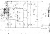
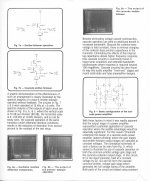
Schematic is attached. You can lower the gain in numerous places.
Loading the output of the MC preamp to ground with 1 Kohm where the
15K is will take about 7-8 dB.
Or you can increase the value of the 750 ohm to ground in the feedback
loop of the high level stage.
Loading the output of the MC preamp to ground with 1 Kohm where the
15K is will take about 7-8 dB.
Or you can increase the value of the 750 ohm to ground in the feedback
loop of the high level stage.
Attachments
Schematic is attached. You can lower the gain in numerous places.
Thank you very much Nelson (very gentleman) I will treasure these valuable tips regarding the modifications of the SL 10 that I will carry out as soon as possible and will read the attachments you have included regarding the CAS power amplifiers; I really hope to find an answer for this power amplifier in your attachments becouse in the instruction manual someone says that there are indications on which speaker connection cables to use "recommended by the factory" (perhaps the least capacitive possible or containing a resistive / capacitive network inside?) to avoid having problems with the power amp.
I am very enthusiastic about your products that I also own a Xono (not diy) that I have been using with enormous satisfaction for over 15 years that does not need any modification, it is perfect like that.

Last edited:
I don't recall the amplifier having any issues with cables, but the only examples
that might be suspect are Litz wire and Mogami coaxial without the RC
terminations at the speakers.
that might be suspect are Litz wire and Mogami coaxial without the RC
terminations at the speakers.

Hi, reviving an old thread here.
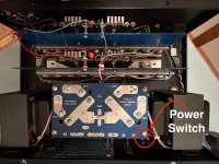
I bought a CAS-2 amp a couple years ago with the idea of using it to learn about audio electronics. Well, that time has come. A cabinet door depressed the power button on it overnight so it appears it was cycling on and off throughout the night. Now the right channel is significantly reduced in power; sound still emits from the speaker but my guess about 80% reduced. The image of the switch is before I re-soldered it.
I've spent a few hours scouring Mouser for a replacement switch. As my background in circuits is limited, can I buy a DPST with only four terminals as opposed to the six on the existing switch? I can read motorcycle wiring diagrams but audio circuits I'm not confident.
I didn't write down the existing panel cut out dimensions but if I remember correcty it's about (30mm X 22mm). I'm looking at a couple switches: NKK and C&K. The Amp rating of both switches is 16 vs 10 on the current Carling switch but I cannot find a replacement Carling switch.
My mistake in thinking purchasing a replacement switch would be easy. Anyone have thoughts on this? My apologies for such a basic question but I'm struggling to find an exact replacement and don't want to install anything inferior or potentially damaging to the amp. Thanks in advance.
Attachments
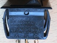
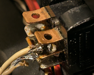
generic rocker switch, you really need just 4 terminals, which is actually 2 separate switches/sections
hope you'll get better soldering job on new one than what's visible on existing
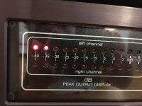
though, I think trouble is way bigger than just a switch, judging by details you gave - 20% of sound in channel and silly display
hope you'll get better soldering job on new one than what's visible on existing
though, I think trouble is way bigger than just a switch, judging by details you gave - 20% of sound in channel and silly display
@Zen Mod, ok, thank you for the info; I'm probably going to purchase the NKK based on specs and dimensions. Yeah, the soldering job in the photo was not my work; I couldn't sleep at night if I soldered something like that.
If the replacement switch doesn't solve the problem it seems I'll be posting here again. Thanks again for the reassurance.
If the replacement switch doesn't solve the problem it seems I'll be posting here again. Thanks again for the reassurance.
Ok, so, I double checked the power switch and it's fine. I did find a mangled capacitor on the right channel input stage (yellow one in photo) that I'm going to replace. The existing capacitor is an Axial with markings of SEC 79-39 PPxx (xx means I can't tell what it says) 100V .001/1nf/1000pf +-2% but I'm having trouble finding a replacement (newbie here). Based on the specs I figured it's a Film capacitor.
I found THIS capacitor on Mouser but it's 10% tolerance. I found some on Kemet but they were 5% tolerance listed as for automotive use and out of stock anyhow. I checked amprepairparts.com but couldn't find the same specs. I've googled, used chatgpt and searched this forum and can't find a place to purchase capacitors based on these specs.
Does anyone know a website, store or other place to purchase this type of capacitor? Thanks in advance.
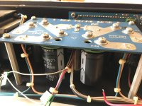
I was able to source the film capacitors and finally pull the boards from the amp. I found a couple electrolytic capacitors that were bulging so decided to replace all capacitors (including the power supply). I now realize that was a mistake; I should have been methodical in approach. The right speaker is fine, however, the left one now has distortion. I swapped the pre-amp inputs to the amp but the left speaker still had distortion so I swapped the left and right speaker cables at the amp and the distortion moved to the right speaker. Ok, so left channel issue.
From the hours of Ytube videos, ai suggestions and forum research this can be many things but I'm hoping for a bit of direction on where to start. The shop where I bought the capacitors checked them before selling them to me but they did it behind the counter so I took their word for it. I'm hoping for a bit of guidance as I'm pulling my hair out trying to solve the problem. I originally thought it was a ground issue because I had put Deoxit L260d grease on the input stage grounds and under the power supply capacitor screw mounts to keep oxidation down. I went back and cleaned all the grease off but it didn't remove the distortion.
Maybe there's an obvious reason for the distortion that a newbie like me is missing? Is it simply a bias issue after recapping, an overheated capacitor while soldering, or something else that I'm not aware of?
Hoping for a little help. I realize my last post was ultra basic but not having any prior audio electronic repair experience makes every step full of hours of research to understand what one is looking for and also what one needs to purchase.
For any noob in the same boat as me, check your work! Before pulling the boards again (which involve de-soldering about six wires) I decided to use a multimeter to check for continuity on the circuits.
I assumed the distortion was from a bad component like a transistor, capacitor or resistor but it turned out to be one wire connecting the input to the output stage. I had soldered the wire in and it visually looked fine but when I tested the exposed wire on the back of the un-traced board to the circuit on the other side it was OL.
The CAS-2 is alive again! The moment was 50% joy and 50% relief. This really is diy audio, lol.
Last edited:
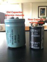
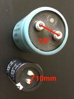
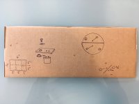
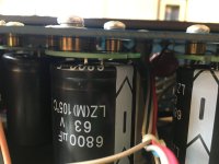
One last thing on this project/repair, I couldn't find replacement filter capacitors with the same 6900 micro farad, 60 Volt specification, especially with screw mount terminals 7/8" apart. So I bought a copper clad circuit board and was going to etch my own circuit (cardboard drawings) but didn't want to deal with the hazardous waste created afterward.
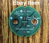
The key phrase to search for is: capacitor adapter. I found a gentleman on fleabay that sells a perfect fit and function item that allows a snap pin capacitor to attach via the original screw mounts. I attached a couple photos of it: the capacitors hang down from the pcb but are solidly attached. I can't express enough how much this small item made a difference for me.
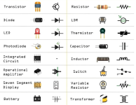
I included an electronic symbols chart just in case anyone new to this like me that may need a reference; the column on the left is the 'Active' and the right is the 'Passive'. Hope it helps someone!
The key phrase to search for is: capacitor adapter. I found a gentleman on fleabay that sells a perfect fit and function item that allows a snap pin capacitor to attach via the original screw mounts. I attached a couple photos of it: the capacitors hang down from the pcb but are solidly attached. I can't express enough how much this small item made a difference for me.
I included an electronic symbols chart just in case anyone new to this like me that may need a reference; the column on the left is the 'Active' and the right is the 'Passive'. Hope it helps someone!
Attachments
- Home
- Amplifiers
- Pass Labs
- Threshold CAS-2 poweramp